WhatsApp:+86 18005022363 WeChat: +86 18005022363
  Email:
Technical Specifications
| Parameter Name | Parameter Value |
|---|---|
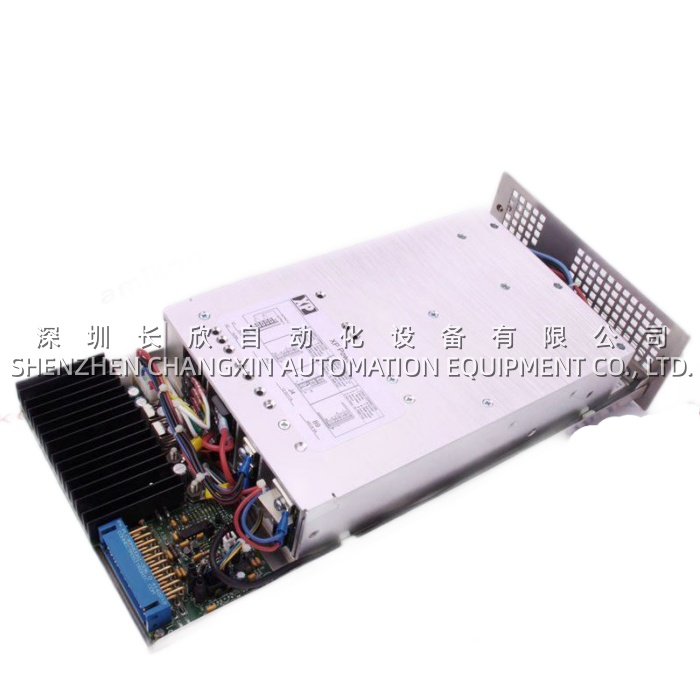
| Product Model | 3BHE032025R0101 (PCD235A101) |
| Manufacturer | ABB (Power Generation – Excitation Systems) |
| Product Type | Exciter Control Module (Regulator CPU, PCD series) |
| Compatible Systems | UNITROL 5000, UNITROL 6000 (excitation); some PEC-derived retrofits |
| Predecessor | CM_T series (CM4, CM5) regulator CPUs |
| Peer / Rack Siblings | UNS0882A-P V1 PSI (3BHB006309), UNS2881B-P V1 MUB (3BHE009319), UAD206 A101 (3BHE019958) |
| CPU | Motorola/Freescale 68K-class or PowerPC (PCD235 era, ~2005–2015 BOMs) |
| Memory | Flash (firmware) + RAM (runtime) + NVRAM (AVR/PSS/limiter parameters, retains through power loss) |
| Regulation Functions | AVR (Auto: Vterm; Manual: Ifield), PSS (IEEE 421.5, ΔP or Δω input), OEL (thermal), UEL (stability), V/Hz (flux) |
| Communication (Plant) | RS-232 (local terminal), RS-485 (Modbus RTU), optional Profibus DP; later BOMs offload plant comm to UAD206 |
| Communication (Gate Drivers) | 2–4 × fiber ports (ST/LC), firing-angle command to thyristor gate-driver ring (UFC719 / 3BHB003387 class) |
| Backplane | Proprietary UNITROL rack backplane (to PSI, MUB, UAD206) |
| Supply Voltage | 24 V DC (20–30 V window) from PSI |
| Power Consumption | ~10–15 W |
| Operating Temp. | -20 °C to +60 °C (exciter-cabinet envelope) |
| Storage Temp. | -40 °C to +85 °C |
| Mounting | Card cage / backplane (UNITROL rack) — not DIN |
| Dimensions | ~250 × 35 × 30 mm (L × D × H, card-cage format) |
| Weight | ~0.5–0.8 kg |
| Protection | IP20 (rack-mounted) |
| Agency | CE, UL, RoHS |
Main Features and Advantages
AVR + PSS + limiters in one regulator CPU. The PCD235A101 is purpose-built for generator excitation — not a generic PLC with an AVR add-on. The firmware implements:
- AVR Auto mode: terminal V regulation via PT feedback (from MUB), PI with lead-lag compensator, typically 10–20 ms scan → generator V held ±0.5 % steady-state.
- AVR Manual mode: field-current (Ifield) regulation via CT feedback (from MUB), used during commissioning, stator-earth-fault events, or when PT fails (auto→manual bumpless transfer, tracked continuously — the PCD keeps Manual output tracking Auto so the switch doesn’t bump excitation).
- PSS (Power System Stabilizer): IEEE Std 421.5, ΔP (speed-matched active-power deviation) or Δω (speed deviation derived from Vterm zero-cross on MUB) input, washout + lead-lag + gain, damps ~0.2–2.0 Hz inter-area oscillations. On a 500 MW unit tied to a weak grid, the PSS contribution is what keeps the unit from oscillating with its neighbors — the PCD235A101’s PSS gains are tuned during site commissioning and stored in NVRAM.
- Limiters: OEL (over-excitation, generator thermal I²t model per IEEE 421.5, e.g., 130 % for 60 s, 150 % for 30 s), UEL (under-excitation, stability-limited, Q-min curve), V/Hz (overflux protection, V/f > 110 % → reduce excitation). The PCD235A101 arbitrates these against the AVR output (lowest-wins for underexcitation, highest-wins for OEL/VHz depending on direction) — this arbitration is what prevents the generator from overheating (OEL) or losing synchronism (UEL) during a grid disturbance.
Redundant 1+1 PCD configuration (common on critical units). Many UNITROL 5000/6000 BOMs on 300+ MW units carry two PCD235A101 in the same rack — Primary and Standby, hot-idle, NVRAM mirrored or at least parameters matched. If Primary fails (CPU lockup, NVRAM corruption, backplane fault), the Standby takes over bumpless — the generator never loses excitation. For plants with single-PCD BOMs (cost-cut), upgrading to 1+1 during a turnaround (add second PCD235A101 + mirror params) is a common life-extension. The PCD235A101’s “Redundancy Status” LED + backplane handshake makes the bumpless switch transparent to the plant DCS (<100 ms, no AVR output bump).NVRAM parameter persistence — and the trap. The PCD235A101 stores the AVR/PSS/limiter tuning in NVRAM (some BOMs also have a coin-cell for SRAM retention, depending on era). This is the PCD’s biggest sparing consideration: if you swap a failed PCD235A101 and the NVRAM is blank (new board, or corrupted old board), the replacement boots with default AVR gains — not the site-tuned ones. Connecting a default-PCD to a live 500 MW unit and enabling AVR = generator V oscillates or over/under-shoots → grid event. Correct procedure: before any PCD swap, export the parameter set from the live PCD (via ABB’s Excitation ToolSuite / DriveIT / PU-tool — depending on BOM vintage) to a laptop / plant server / USB. After swap, download the param set to the new PCD235A101, verify Auto/Manual tracking, then release to “Auto” from “Manual local.” MRO teams that skip the param backup create 4-hour outages — this is the #1 “swap looked easy but became a mess” story on UNITROL fleets.Fiber ports to gate-driver ring. The PCD235A101 has 2–4 fiber Tx ports (ST or LC) that fire the thyristor bridge gate drivers (UFC719 / 3BHB003387 class, covered in an earlier thread topic — that board is the IGCT/thyristor gate-driver co-processor that sits in the power stack, PCD235A101 → fiber → UFC719). The fiber isolation is critical: the gate-driver side sits at thyristor cathode potential (several kV during commutate), the PCD sits at 24 V DC control ground — fiber is the only safe coupling. The PCD firmware includes firing-pulse supervision: if a fiber CRC fails or a gate-driver returns a “desat” flag, the PCD trips the thyristor bridge (block firing) and flags “Excitation Fault” to the turbine governor/DCS.Hot-swap in redundant pair. When the mate PCD is alive, the PCD235A101 extracts/reinserts without disturbing excitation — the rack backplane keeps the mate alive, parameters sync (or at least the mate covers while the new PCD boots and loads params). Swap time ~10 minutes + param download. Single-PCD racks can’t hot-swap safely — the rack loses AVR during the swap → generator must be off-load or at least “manual-excite” from a separate exciter (rare). Hence single-PCD units schedule PCD swap during a planned outage; redundant-PCD units can swap online.
Application Field
The PCD235A101 deploys exclusively on generator exciters — the application map follows ABB UNITROL’s global installed base:
- Thermal power (coal, combined-cycle, biomass) 100–1000 MW: UNITROL 5000 on the turbogenerator (often two per unit — main exciter + pilot exciter, or one 3-phase thyristor bridge feeding the rotor). The PCD235A101 is the AVR CPU. In a 500 MW CC unit, a PCD failure + no redundant mate = generator trips off excitation = grid event + NERC reportable + ~50k–500k depending on duration and market. In peaking plants (start/stop daily), the PCD sees more thermal cycling (exciter cabinet runs 45–55 °C from thyristor bridge convection) → aging accelerated vs baseload.
- Hydro 10–500 MW: UNITROL 5000 or 6000 on the hydro-generator. Multiple units per plant, each with its own PCD235A101. Hydro units ramp frequently (load-following, spot-market), so the AVR+PSS gets exercised more than thermal baseload — PCD firmware sees more mode-transitions (no-load → grid-tie → full-load → governor-droop engagement). PSS tuning on hydro is critical because hydro plants are often the damping contributors on weak grids (Nordic, Brazilian, Canadian) — the PCD235A101’s PSS gains are site-unique.
- Nuclear auxiliaries & pumped-storage: UNITROL 6000 (larger, more redundant) on the main generator, PCD235A101 or newer PCD236. Pumped-storage units reverse (generator→motor→pump), so the AVR must handle four-quadrant operation — PCD firmware supports this; the MUB measurement and the gate-driver firing both reverse-polarity aware.
- Synchronous condensers: Grid-stability assets (increasingly deployed for renewable-host grids), often retrofitted with UNITROL 5000 + PCD235A101. Condenser mode = no active power, pure Q support — AVR regulates Vterm, PSS may be disabled or re-tuned, limiters still active.
Retrofit and service context: UNITROL 5000 + PCD235A101 installs peaked ~2005–2015 (PCD235 A101 is a mid-life revision; earlier PCD235 A00, later PCD236 on UNITROL 6000 / latest UNITROL 5000). Age now 10–20 years. Aging mechanisms: (1) NVRAM wear / coin-cell death (params lost on power loss → “PCD NVRAM Error” alarm), (2) CPU-bridge electrolytic (5 V / 12 V rail on the PCD sags → CPU lockup under load, manifest as “AVR Watchdog Trip” — generator drops excitation mid-shift), (3) fiber-TX degradation (optical power at the gate-driver falls below threshold → “Firing Pulse Loss” on one thyristor leg). ABB’s Excitation Care recommends proactive PCD refresh at ~18 years for critical units, and always export params before any swap. For plants mid-migrating to UNITROL 1020 (successor platform, fiber-digital, different CPU — not PCD-series), the PCD235A101 is the interim spare during the cutover (old UNITROL 5000 rack stays live while 1020 is commissioned on parallel cubicle — 12–18 month window where PCD spare is still needed).