WhatsApp:+86 18005022363 WeChat: +86 18005022363
  Email:
Application Scenarios:
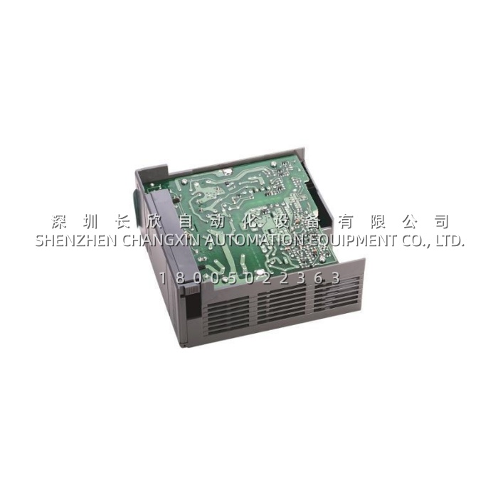
A cement plant ran a 13-slot 1746-A13 chassis on a SLC 5/04, and over fifteen years the rack had filled up incrementally: dense relay output cards, several analog input modules, a thermocouple card, an Ethernet communication adapter, and a high-speed counter. Nobody recalculated the backplane budget after each addition, because each individual addition was small. Then the plant began experiencing a specific and disturbing symptom — during high-production periods, when the kiln induced draft fan and the raw mill drives started, the CPU would occasionally fault, and on two occasions the program was lost entirely, requiring a reload from a backup that was itself months old.The investigation did not find a failing CPU. It found a 1746-P2 sitting in a rack whose 5 V load had quietly grown past 5 A. The supply was not dead — it was marginal. Under normal conditions it held; during plant-wide voltage dips caused by large motor starts, its 5 ms full-load hold-up was not enough to ride through, and the backplane sagged below the processor’s operating threshold. The leading indicator, a slow drift in the 5 V rail during periods of high scan loading, had been present long before anyone measured it.The fix was a 1746-P4 plus a load calculation. At 10 A on the 5 V rail and 2.88 A on the 24 V rail, the supply restored roughly a 40% margin over measured demand, and its 20 ms full-load hold-up — four times that of the P2 — absorbed the dips that had been resetting the processor. The spurious major faults stopped, and the plant added a periodic 5 V rail measurement to its PM routine.This is the role the 1746-P4 plays across the installed SLC 500 base. It is the answer when a chassis has grown: fully populated 10-slot and 13-slot racks, panels dense with analog and specialty modules, racks carrying Ethernet or ControlNet communication adapters, and any SLC 500 system that has been expanded over years without a backplane budget review. It is also the standard remedy for intermittent, load-dependent faults that are frequently misdiagnosed as CPU or module failures — brownouts, unexplained major faults, program corruption at the battery threshold, and modules dropping off during motor starts.
Parameter:
| Main Parameters | Value/Description |
|---|---|
| Product Model | 1746-P4 |
| Manufacturer | Allen-Bradley (Rockwell Automation) |
| Product Category | High-Capacity Rack-Mounted Chassis Power Supply (SLC 500 / Bulletin 1746) |
| Input Line Voltage | 85–132 V AC or 170–265 V AC, jumper-selectable on a two-position header beside the input terminal block |
| Input Frequency | 47–63 Hz — usable on 50 Hz and 60 Hz mains worldwide |
| Backplane Capacity at 5 V DC | 10.0 A — the highest in the 1746 AC supply family; determines how many logic loads the chassis can carry |
| Backplane Capacity at 24 V DC | 2.88 A — feeds the 24 V backplane circuits used by analog, specialty, and output modules |
| User 24 V DC Output | 1.0 A maximum, isolated, 18–30 V DC range (20.4–27.6 V DC nominal range) — an auxiliary branch for approved field circuits |
| Combined Output Power Limit | 70 W maximum across all outputs (5 V backplane + 24 V backplane + 24 V user source) — the constraint that governs real usable capacity |
| Typical Line Power Requirement | 240 VA apparent input power |
| Maximum Inrush Current | 45 A — must be allowed for when sizing upstream breakers, contactors, and switching devices |
| Maximum Input Power | 92 W |
| CPU Hold-Up Time | 20 ms at full load; 3000 ms at no load — ride-through that protects the processor during brief mains dips |
| Isolation | 2600 V DC for 1 s input-to-output; fully isolated from the PLC electronics |
| Fuse Protection | Internal soldered-in fuse guards against fire hazard from short-circuit conditions; not a user-replaceable service part |
| Indicators | LED power indicator for at-a-glance confirmation of supply operation |
| Mounting | Left-most slot of any 1746 modular chassis (1746-A4, -A7, -A10, -A13); mounts on the same two tabs as the P1 and P2 |
| Input Wiring | Up to 2 × 14 AWG per terminal |
| Operating Temperature | 0 °C to +60 °C (+32 °F to +140 °F); current capacity derated 5% above +55 °C |
| Storage Temperature | -40 °C to +85 °C |
| Hazardous Location Rating | Class I, Division 2, Groups A, B, C, D |
| Certifications | UL Listed (Industrial Control Equipment), CSA Certified, CE compliant for applicable directives |
| Weight | Approx. 1.1 kg (2.45 lb) — noticeably heavier than P1/P2 due to the larger internal transformer |
| Dimensions | Approx. 16.6 × 4.2 × 11.8 cm (6.53 × 1.65 × 4.64 in) |
| Country of Origin | Mexico |
| Lifecycle Status | Discontinued by Rockwell Automation; available through surplus, refurbished, and new-old-stock channels |
Technical Principles and Innovative Values:
- Innovation Point 1 — Highest backplane capacity in the family: At 10.0 A on the 5 V rail and 2.88 A on 24 V, the 1746-P4 delivers double the 5 V current of the P2 and five times that of the P1. In a fully populated 13-slot chassis where dense output cards, analog modules, and communication adapters are summed slot by slot, this capacity is what makes the configuration possible at all rather than merely comfortable.
- Innovation Point 2 — Four times the ride-through of the alternatives: The 1746-P4 provides 20 ms of hold-up at full load versus 5 ms for the P2. That difference is the entire margin between a processor that rides through a plant-wide voltage dip caused by a large motor start and one that faults and potentially loses its program. It is the specification that matters most in plants with soft starters, large drives, or weak utility feeds.
- Innovation Point 3 — Jumper-selectable dual-range input for global use: A two-position header beside the input terminal block selects 120 V AC (85–132 V) or 240 V AC (170–265 V) operation, at 47–63 Hz. The 1746-P4 therefore ships worldwide on a single part number, and panels built in one region can be deployed in another without a different supply. Rockwell ships it in the 240 V position, and a wiring diagram on the housing reminds the installer to verify before energizing.
- Innovation Point 4 — Isolated auxiliary 24 V branch: Unlike several siblings, the 1746-P4 provides a 1 A isolated 24 V DC user output in the 18–30 V DC range. This lets a panel power an approved field circuit — a sensor, a small relay group, an indicator — from the chassis supply rather than adding a separate DIN-rail unit, provided the load stays inside the shared 70 W budget.
- Innovation Point 5 — 2600 V DC isolation for electrically hostile plants: The 1746-P4 is tested at 2600 V DC for 1 s between input and output. In panels serving kilns, drives, and large contactor banks, that isolation barrier is what keeps mains-side transients from reaching the processor and I/O — a meaningful reliability factor in exactly the heavy industrial environments where SLC 500 systems tend to survive longest.
- Innovation Point 6 — Engineered thermal behavior and the chimney effect: The 1746-P4 carries a substantially larger internal transformer than the P1 or P2 and relies on passive convection cooling. Rockwell’s spacing guidance — at least 152 mm (6 in.) of free clearance above and below the chassis — is not a suggestion; trapping heat at the top of the supply degrades the internal electrolytic capacitors and shortens service life. Slot fillers in empty slots preserve the engineered airflow tunnel.
- Innovation Point 7 — Class I Division 2 certification: Certified for Class I, Division 2, Groups A, B, C, D hazardous locations, the 1746-P4 can be installed in classified areas where many general-purpose industrial supplies cannot — a decisive factor for oil and gas, chemical, and grain handling panels.