WhatsApp:+86 18005022363 WeChat: +86 18005022363
  Email:
Description:
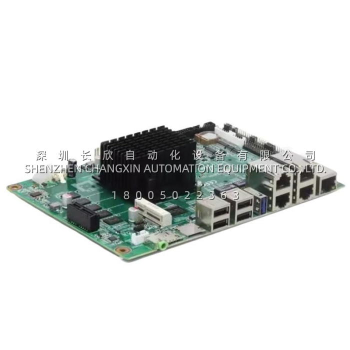
The GE 531X113PSFARG1 is a power supply interface card from General Electric, part of the 531X family of plug-in boards used inside GE drive control cabinets and Speedtronic Mark V turbine control racks. It is a power distribution and signal conditioning board — the central node that sits between the cabinet’s DC supply and the processor, I/O and function cards that depend on it.In practical terms, 531X113PSFARG1 takes the incoming DC rail and distributes it to the other cards in the rack through six vertical pin headers, while filtering and conditioning the signals that pass across it. Onboard fuses, relays, inductor coils and heat-sinked power components handle protection and thermal duty; six potentiometers, three LED indicators and labelled test points give a technician the means to calibrate and diagnose the board in place. It is not a general-purpose power module — it is a cabinet-specific interface board built for one architecture.
Application Scenarios:
A steel plant’s main rolling mill runs on a legacy GE DC drive, and the control cabinet has started behaving badly. Processor resets. I/O dropouts. Faults that appear under load and vanish when the instrument cart arrives. The maintenance team has replaced the CPU card and two I/O cards, and the problem persists, because the fault is not in any of the cards — it is in the power and signal quality they are all being fed. An oscilloscope on the 24 V DC control bus shows ripple and noise from the high-power thyristor bridge feeding back into the logic supply. Every card downstream is now operating from a compromised rail, and each one is a suspect.This is the failure mode 531X113PSFARG1 exists to address. In this scenario, the board is identified as the culprit — the filtering and distribution stage that is supposed to keep thyristor noise out of the logic supply — and replacing it restores clean power to the processor and I/O cards. Because the board carries six different connector types and the same mechanical form factor as the original, it swaps in without rewiring. The erratic faults disappear and mill uptime returns. The pain point is diagnostic, and it is expensive: intermittent power-quality faults send maintenance teams replacing perfectly good cards while the actual cause sits upstream, quietly corrupting everything it feeds.
Parameter:
| Main Parameters | Value/Description |
|---|---|
| Product Model | 531X113PSFARG1 (531X series; equivalent internal board marking in the F31X___ form) |
| Manufacturer | General Electric (GE Power / GE Vernova legacy drive and turbine control line) |
| Product Category | Power supply interface card — DC power distribution, signal interface and voltage conditioning for drive control cabinets |
| Compatible Platforms | GE 531X series drives; Speedtronic Mark V control systems; DC300 and DC2000 DC drives; commonly cited alongside EX2000 excitation and turbine auxiliary panels. Verify against your cabinet schematic |
| Input Voltage | 24 V DC typical (18–30 V DC range) per most sources. Note: other listings describe 115/230 V AC input variants in this board family — the board label and cabinet schematic are authoritative |
| Current Consumption | Up to 210 mA (board’s own draw, not its distribution capacity) |
| Output Rails | Distributes the regulated DC rails used by 531X logic cards — typically +5 V DC (digital logic), ±15 V DC (analogue and op-amp circuits) and +24 V DC (relays, terminals, external signals). Exact rail set depends on cabinet configuration |
| Connector Configuration | Six vertical pin male cable headers: 1 × 2-pin, 1 × 4-pin, 2 × 6-pin, 2 × 9-pin. Mixed pin counts key the harness so connectors cannot be transposed |
| Adjustment & Calibration | Six potentiometers, for field adjustment of signal levels such as speed feedback scaling, current limits and feedback zero/gain without touching the CPU card |
| Protection Components | Three onboard fuses, three relays, six inductor coils, MOVs and TVS devices for overcurrent, surge and overvoltage protection |
| Passive & Active Components | Metal film and carbon composite resistors; polyester/vinyl and electrolytic capacitors including large electrolytic reservoir capacitors; over ten resistor network arrays; multiple ICs; transistors |
| Thermal Management | Three heat sinks, coupled to the inductor coils and power components — passive convection, no fan on the board |
| Diagnostics | Three LED indicators plus labelled TP test points for in-situ voltage and ripple measurement |
| Physical | Approximately 24 cm × 29.2 cm × 4 cm (board footprint in the standard 531X / Mark V format, roughly 240 × 292 mm); approximately 0.58 kg |
| Construction & Mounting | Multi-layer FR-4 PCB with conformal coating; corner mounting holes for screw fixing in the drive cabinet subrack; plugs into the cabinet backplane or harness |
| Environmental | Typically −20 °C to +70 °C operating (some sources cite 0 °C to +60 °C); IP20 for enclosed cabinet installation |
| Lifecycle Status | Discontinued (legacy) — available only as new surplus or refurbished stock |