WhatsApp:+86 18005022363 WeChat: +86 18005022363
 Email:

Application Scenarios
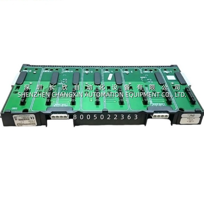
A brownfield refinery tank-farm upgrade had a familiar constraint: the control-room marshalling cabinet was full, the I/O list was still moving, and running a new 50-pair home run for every added level transmitter meant opening a tray that the operations team refused to touch during the turnaround window.The project skipped the marshalling cabinet entirely. A VE4060C1 went into a small field enclosure at the tank manifold, its extension cable routing the backplane to a DIN run that actually fit the space. Eight CHARMs dropped in as the list settled — 4–20 mA HART for the radar gauges, a dry-contact DI for the high-high float, and a couple of spares left empty on purpose. The CIOC upstream was already dual-homed on redundant Ethernet, and the 24V feed was A and B, so a blown fuse or a chopped cable never took the whole manifold offline. When the operations team later added a steam-traced line and needed an RTD point, a technician seated the new CHARM, the system “electronically marshalled” it to the same controller, and the control-room cabinet was never entered.The panel builder’s summary was the whole point: “We didn’t run a single new wire to the control room.”That is the VE4060C1‘s job — not to be smart, but to make the smart part of CHARMs2 cheap to deploy.
Parameter
| Parameter | Value / Description |
|---|---|
| Product Model | VE4060C1 |
| Manufacturer | Emerson, Discrete Automation & Process Systems (DeltaV DCS) |
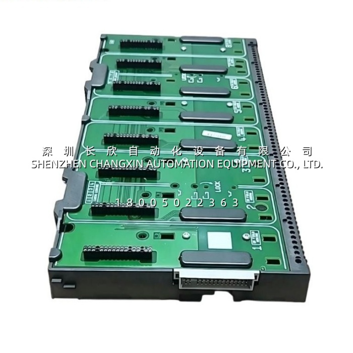
| Product Category | CHARMs2 8-wide I/O carrier / backplane assembly (passive carrier — contains no I/O intelligence of its own) |
| Also Listed As | VE4060C1 KJ410X1-BA1, internal/plant number 12P1870X012. Both marks appear on procurement records; confirm both when matching a legacy spare to a new PO |
| Architecture | DeltaV Electronic Marshalling, CHARMs2 generation. Bays connect to a CIOC (CHARM I/O Card) over the carrier backplane; the CIOC owns the Ethernet uplink to the controller |
| Bay Capacity | 8 bays per carrier. Empty bays are valid — the backplane does not need to be full, and a bay can stay spare for the next project change |
| CHARM Mixing | Any CHARMs device type in any bay: AI 4–20 mA / HART, AO 4–20 mA, 0–10V, TC, RTD, DI dry or Namur, DO high-side, relay contact, isolated high-current/high-VAC DI/DO. Signal type is a property of the CHARM, not the carrier |
| Upstream Interface | Redundant Ethernet I/O network via the CIOC. The carrier is the physical path; redundancy lives in the CIOC/network design, and the carrier’s dual-feed and routing must support it |
| Power Distribution | 24V DC, dual-feed / redundant-supply capable on the carrier. The CIOC monitors both 24V inputs and temperature, and raises a proactive alarm on the first one to drift — no silent half-dead bus |
| Hot-Swap Capability | Yes — CHARMs devices can be inserted and removed with the carrier powered, and the backplane is designed so a single-bay swap does not disturb its neighbours. The carrier itself is a field-replaceable unit; coordinate the swap with the CIOC bay-map procedure |
| Extension Cable | Included with the C1 variant (this is the defining C0/C1 difference). Lets the carrier body and the bay/connector footprint be positioned independently, which is the whole reason this part exists in tight or remote enclosures |
| Mounting | Cabinet / panel / DIN-rail style mounting, in the horizontal 8-wide orientation. Route and dress the extension cable before the final fasteners — re-positioning later means re-opening the bay terminations |
| Environmental | 0 °C to +60 °C operating in the published carrier listings; storage –40 °C to +85 °C; 5–95% RH non-condensing. Note the CIOC is rated –40 °C to +70 °C, so do not infer the carrier shares that full low-end range — design to the carrier’s 0 °C floor |
| Protection | IP20, open-style, cabinet-mounted only. The CHARMs devices themselves carry the hazardous-area rating (Class I Div 2 / Zone 2, Groups A–D where licensed), not the carrier |
| Dimensions | Published figures conflict: 107 × 41 × 105 mm in the KJ410X1-BA1 records, 336 × 31 × 165 mm in the 8-wide carrier listings. The smaller figure is the carrier body; the larger almost certainly includes the extension-cable and connector footprint. Use the 336 mm envelope for cabinet clearance and the 107 mm figure only for the body itself |
| Weight | Likewise split in the channel: ≈0.18 kg for the body, ≈0.56 kg boxed with the extension cable and fixings. Count 0.56 kg for DIN-rail and seismic load calc |
| Country of Origin | USA in the current procurement records |
| Diagnostics | No on-board processor, so no standalone diagnostics — health is reported by the CIOC: 24V A/B status, temperature, backplane link and per-bay CHARM presence. A “carrier fault” in the alarm list almost always means power, seating or the extension-cable run, not the FR4 |
| Agency / Ratings | Procurement records list COO documentation and industrial-grade construction. The carrier itself carries no independent hazardous-area certificate; the system rating flows from the installed CHARMs and the enclosure |
Two ordering notes before you cut the PO. C0 vs C1 is a cable, not a revision: VE4060C0 is the same 8-wide carrier without the extension cable; VE4060C1 ships with it. If your panel layout was drawn around the cable, buying a C0 saves nothing and costs a day. Second, the KJ410X1-BA1 / 12P1870X012 markings are the plant-side aliases — a spare that “looks like a VE4060C1” but carries a different internal number may still seat, but your MOC and spare-room label won’t match. Photograph the nameplate before you reorder.
Technical Principles and Innovative Values
Innovation Point 1 — The carrier stays dumb so the I/O can stay flexible. The VE4060C1 has no firmware, no configuration and no opinion about signal type. Every bay is electrically neutral, and the intelligence lives in the CHARM and the CIOC. That separation is why a single spare carrier covers AI, AO, TC, RTD, DI and DO — and why a late change order no longer rewrites the panel layout.Innovation Point 2 — Electronic marshalling replaces a roomful of terminals. Traditional I/O forces you to decide, at design time, which field wire lands on which card in the control room. CHARMs2 moves that decision into software: land the wire on the nearest VE4060C1, seat the right CHARM, and “marshall” the channel to whichever controller needs it. No cross-wiring, no marshalling cabinet, no “we can’t add a point there because the tray is full.”Innovation Point 3 — Mixed signal types on one backplane, with isolation per channel. Because each CHARM is its own isolated, single-channel device, putting a 4–20 mA HART gauge next to a 240VAC isolated DI on the same VE4060C1 is not a rule violation — it is the intended use. The carrier supplies the common backplane; the CHARM supplies the isolation. That is how a field enclosure drops from “one terminal block per signal family” to “one carrier, eight bays, done.”Innovation Point 4 — The extension cable is a layout tool, not an accessory. The C1’s included cable lets the VE4060C1 body sit where the DIN rail is, while the business end reaches the conduit entry or the heater-jacketed zone that dictated the original routing. In a retrofit, that single cable is often the difference between “we need a new enclosure” and “we fit it in the existing one.”Innovation Point 5 — Redundancy you can actually repair at 2 a.m. Dual 24V feeds, redundant Ethernet through the CIOC, and per-bay hot-swap mean the failure domains are small and individual. A CHARMs device dies, you pull it; a 24V leg sags, the CIOC already told you which one; the carrier itself is a five-minute bench-swap. Nowhere in that list does anyone need to touch the control-room cabinet.