WhatsApp:+86 18005022363 WeChat: +86 18005022363
  Email:
Technical Specifications
| Parameter Name | Parameter Value |
|---|---|
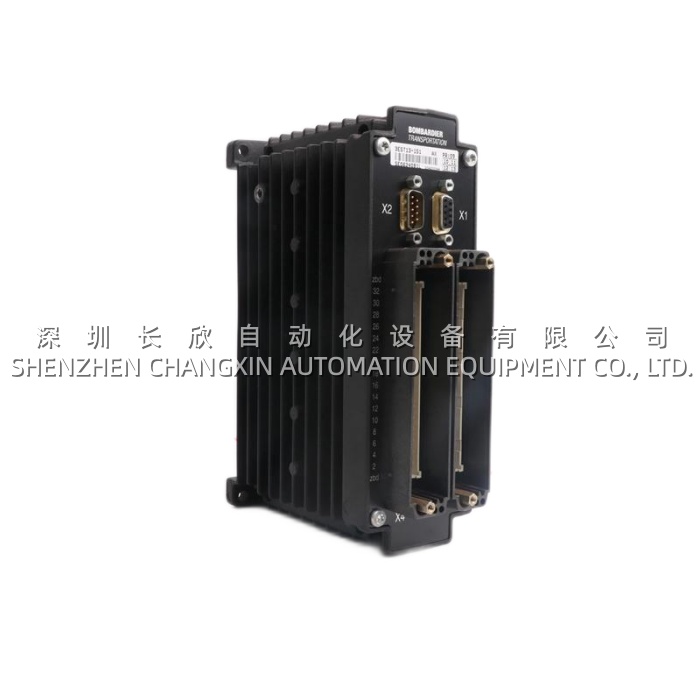
| Product Model | 3EST13-151 (Commercial: DCA2000A) |
| Manufacturer | Bombardier Transportation (now Alstom Mobility) |
| Product Type | Analog Input Module (Vehicle-Borne, Train I/O) |
| Platform | BT MITRAC / ORION / CITYFLO vehicle control (car-body I/O rack) |
| Channels | Typically 8 or 16 analog inputs (BT DCA2000 family: 8-ch common, verify per BOM) |
| Input Types | 4–20 mA DC (active/passive loop), 0–10 V DC, optionally 0–5 V / 1–5 V |
| Input Impedance | Current: 250 Ω (typical, internal) / Voltage: ≥ 1 MΩ |
| Resolution | 12–14 bit per channel (BT DCA2000 generation) |
| Accuracy | ±0.3% full-scale typical (25°C), ±0.5% over –25°C to +70°C |
| Conversion Cycle | ~10–50 ms per scan (synchronised to MVB process data cycle, typ. 16–32 ms) |
| Communication | MVB Slave (IEC 61375-3-3), 1.5 Mbps, process data telegrams |
| Alternative Bus | CANopen LSS/PDO on some CITYFLO/ORION variants (verify per vehicle BOM) |
| Supply Voltage | Vehicle battery: 24 V DC (saloon rack) or 74/110 V DC (bogie/underframe rack) stepped down internally; typical module draw ~3–6 W |
| Mounting | BT vehicle I/O rack (19″ subrack or DIN-profile inside car-body electrical cabinet) |
| Operating Temperature | –25°C to +70°C (saloon/cabinet), –40°C to +85°C (bogie-mounted variants — verify if DCA2000A is saloon or bogie rated) |
| Humidity | 5%–95% RH, non-condensing, with condensation tolerance (railway climate) |
| Vibration / Shock | IEC 61373 Category 1 Class B (saloon) or Class A (bogie) — verify BOM; conformal-coated PCB |
| Protection | IP20 (inside cabinet), IP54 possible if rack has outer shroud (depends on car-body design) |
| Dimensions (approx.) | ~160 × 100 × 20 mm (DCA module profile), rack-dependent |
| Weight | ~0.2–0.35 kg |
| Certifications | EN 50155 (railway electronics), EN 50121 (EMC), EN 45545 (fire/smoke toxicity, HL3 typical) |
Main Features and Advantages
Railway-grade environmental hardening as default. The DCA2000A is built to EN 50155 (electronic equipment on rail vehicles) and IEC 61373 (vibration/shock) — not industrial-grade (IEC 60721-3-3), railway-grade. That means the PCB is conformal-coated (polyurethane, typically 50 µm), the connectors are vibration-lock (often Harting Han or TE heavy-duty, keyed), the power input has reverse-polarity and surge protection (110 V DC battery can see load-dump spikes from compressor start, the DCA2000A‘s internal DC/DC absorbs it), and the operating envelope covers –25°C (Northern Sweden DMU in January) to +70°C (electrical cabinet behind the driver’s desk in Athens metro in July). For a depot engineer, this means the 3EST13-151 doesn’t fail because the train sat overnight at –18°C — it fails (rarely) because of connector oxidation after 12 winters of road salt aerosol.Native MVB integration without gateway. The DCA2000A speaks MVB slave natively (IEC 61375-3-3), which is the standard vehicle bus on BT’s MITRAC/ORION fleets. The module auto-enumerates on the MVB segment (typically one I/O rack = one MVB slave node, 8–16 modules sharing the node address), and the VCU sees each analog channel as a 2-byte process-data word in the MVB telegram — no OPC wrapper, no Profibus gateway, no “why is my AI not in the VCU tag list” mystery. The DCA2000A‘s channel-to-MVB mapping is done in the vehicle’s TMS engineering tool (Bombardier’s “MITRAC Engineering” or “ORION Configurator”) — each DCA2000A channel gets a signal name (e.g., “Bogie1_BearingA_Temp”, “BC_Pressure_Front”), a range (4–20 mA = 0–150°C or 0–10 bar), and alarm limits (Alert / Danger) that the VCU’s application logic consumes. If you swap a DCA2000A for another DCA2000A (same 3EST13-151), the MVB node ID is on the rack backplane or set by DIP — the VCU re-enumerates on next power-up and the signal names map back correctly provided the channel wiring is identical (which it is in a like-for-like swap).Mixed-range per channel, 4–20 + 0–10 on same module. The DCA2000A typically allows mixing on the same 8/16-ch module: channel 1 = 4–20 mA (brake pressure, 0–10 bar), channel 2 = 0–10 V (HVAC supply temp, 0–50°C mapped), channel 3 = 4–20 mA (bearing temp, Pt100→4–20, 0–150°C), channel 4 = 4–20 mA (fuel level, 0–100%). The range per channel is software-configured in the TMS tool (gain/bias loaded to the DCA2000A’s EEPROM during vehicle commissioning) — no jumper, no DIP, no resistor change. For a DMU with 6 AI loops (brake, pantograph, 2× bearing, fuel, compressor-discharge) + 2 spares, one DCA2000A (8-ch) covers it, and the 0–10 V HVAC temp can share the same module with the 4–20 mA pressure loops. This density matters on a car-body where the electrical cabinet is ~600 mm wide and houses VCU + TCU + I/O rack + battery charger + circuit breakers — every DIN-profile millimetre counts.Sensor-break and range diagnostics. Each channel on the DCA2000A monitors loop continuity (4–20 mA) or under/over-range (0–10 V). A broken Pt100→transmitter loop (vibration at the bogie bearing pedestal loosens the terminal) reads <3.6 mA (or whatever the BT underrange threshold is, typically 3.6 mA = “sensor break” flag) — the DCA2000A flags the channel “Fault” on MVB, the VCU’s application logic escalates to “Bearing Temp Unavailable — reduce max speed to 80 km/h” (typical BT DMU/EMU fault-tree), and the driver sees a yellow “Limited Performance” on the cab HMI instead of a red “Stop Immediately.” This graceful degradation is why railway I/O spends the extra € vs. industrial — the train is moving passengers, not widgets.
Application Field
The 3EST13-151 (DCA2000A) deploys wherever BT-built rolling stock needs analog monitoring on a per-car basis. A Toronto Rocket (BT-built, 6-car married-pairs, TTC subway) has an electrical cabinet per car-body (3 cabinets per 6-car train, one per married-pair + one middle). Each cabinet houses a BT I/O rack with one DCA2000A (8-ch): channels 1–4 = bogie-bearing temp (2 bogies × 2 bearings, 4 AI, Pt100→4–20), channel 5 = brake-cylinder pressure (front bogie, 4–20 mA from the Knorr-Bremse transducer), channel 6 = pantograph pressure (EMU portion of the fleet, 4–20), channels 7–8 = spare / HVAC supply temp. The MVB ties all three cabinets into the train’s MITRAC VCU (one VCU per 3-car set, redundancy: 2× VCU per 6-car). During a winter storm, if bearing A on bogie 2 spikes to 112°C (normal 65–80°C), the DCA2000A reports 19.2 mA (112°C mapped: 4 mA=0°C, 20 mA=150°C → 19.2 = 112.5°C), the VCU’s bearing-temp logic trips “Bearing Alert” → speed limit 50 km/h, driver HMI yellow, depot gets a “Bearing A2 Hot” event on the TMS remote-monitoring (if the fleet has GSM/GPRS telemetry). The maintenance team pulls the car at the next terminal, swaps the DCA2000A only if the fault is “channel A2 reads 3.2 mA” (sensor break, could be transmitter or wiring) — they’ll megger the Pt100 first, but the DCA2000A channel fault bit tells them which bearing to look at without crawling under all 4 bogies.On a UK Regional DMU (Bombardier Talent 2, 3-car, diesel-electric), the DCA2000A in the motor-car cabinet lands: compressor-discharge pressure (4–20), fuel-level (0–10 V from sender), coolant temp (4–20 from the engine ECU’s analog out), exhaust-temp-bank-A (4–20), bogie-bearing (4× 4–20). The VCU (MITRAC) uses compressor-discharge + fuel-level for the driver’s HMI “Compressor Load %” and “Fuel Remaining km”, and uses bearing + coolant + exhaust for the “Engine Derating” logic (coolant >95°C → reduce engine RPM 5%, exhaust >650°C → reduce fuel-rack). The DCA2000A here is saloon-mounted (cabinet behind driver’s desk, –10°C to +55°C), so vibration is IEC 61373 Cat 1 Class B (saloon), not bogie. Depot spares: 2× 3EST13-151 per 6-DMU fleet (one per depot store, one float between 3 depots) is typical.On a Montréal AZUR metro (BT-built, 9-car, rubber-tired, fully automated / driverless), the DCA2000A is in each car’s underframe cabinet (bogie environment, –25°C to +70°C, IEC 61373 Cat 1 Class A bogie-rated) — harsher than saloon. The road-salt aerosol from the tunnel ventilation (cars pass each other at 45 s headway, piston-effect pushes platform salt-air into the underframe cabinets) accelerates connector oxidation on the DCA2000A‘s Harting Han header. STM (Société de transport de Montréal) depot practice: every C2 overhaul (every 3 years), unplug the DCA2000A rack’s Harting headers, DeoxIT, re-plug, torque. If a DCA2000A channel drifts >1°C equivalent (bearing temp) between quarterly cal-checks (STM does a portable 4–20 source into the field terminal, compares VCU HMI reading), they swap the module. Tested-surplus 3EST13-151 units are the usual source since BT→Alstom transition — new lead from Alstom on 3EST13-151 can be 12+ weeks, and a 9-car AZUR out of service for a DCA swap waiting on a courier is ~CAD 80k/day lost capacity.Retrofit / life-extension: BT fleets commissioned 2006–2014 are now hitting 12–18 years. The DCA2000A is solid-state with no wear, but the A/D hybrid and the MVB PHY chip can age — sporadic “MVB Slave Com Loss” on one I/O rack every few weeks, clears on re-power, comes back 3 weeks later — classic failing DCA2000A PHY. Depot proactively swaps all DCA modules in a 6-car set during a C3 overhaul (5-year) — 6 × DCA2000A + 6 × DCA2000 DI + 6 × DCA2000 DO per train. Because 3EST13-151 is BT-coded, Alstom still supports it but some depots prefer “tested-pull from decommissioned unit + verified” as a cheaper path than new-from-Alstom.