WhatsApp:+86 18005022363 WeChat: +86 18005022363
  Email:
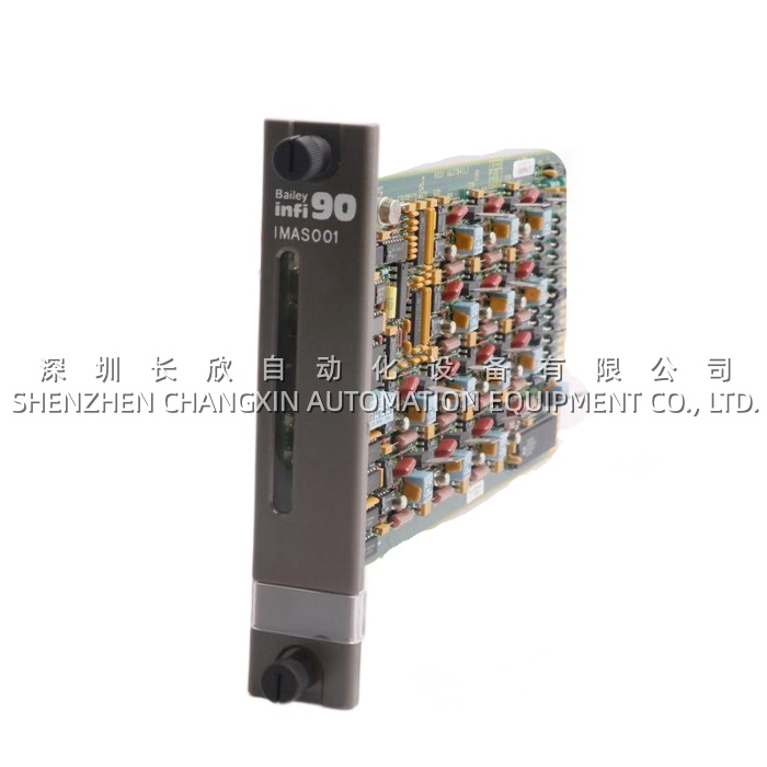
Application ScenariosA 6-stand tandem cold mill in Northern Germany runs a 7.2 MVA ACS6000 (4-quadrant, IGCT) on the main looper. The original gate-chain design ran copper twisted-pair from the firing board straight to each gate unit — six pairs per phase leg × 3 phases = 36 cores in a thick multi-pair cable tray between the control cabinet and the inverter cubicle. During a scheduled maintenance, a contractor re-terminating a neighboring VFD tray accidentally nicked the looper drive’s gate-pair bundle with a screwdriver; one phase-leg pair developed an intermittent short that caused sporadic “Pulse Loss — Phase U Lower” faults at high load (the dI/dt during commutation coupled into the damaged pair). The retrofit replaced the copper run with the GFD233A (3BHE022294R0103) in the control cabinet: the firing source now lands on the GFD233A‘s backplane header, and 12 ST-format fiber pigtails fan out from the GFD233A faceplate to each IGCT gate unit (KUC711) in the inverter cubicle. Because the fiber run is immune to EMI, ground rise, and accidental mechanical damage (plus the GFD233A adds a 4 kV isolation barrier), the “Pulse Loss” fault vanished — and the cable tray fill between cabinets dropped by ~60% because 12 fibers in a ¼” jacket replaced a 36-core armored cable. This case captures the GFD233A‘s value: it’s the optical fan-out that makes a multi-megawatt IGCT stack serviceable and fault-isolated.
arameter
| Main Parameters | Value/Description |
|---|---|
| Product Model | GFD233A (Alt: GF-D233A, Order Code: 3BHE022294R0103) |
| Manufacturer | ABB (ACS6000 MV Drive / IGCT Gate Chain) |
| Product Category | Gate Fiber Driver / Pulse Distribution Interface Module |
| Compatible Systems | ABB ACS6000 (IGCT & high-power IGBT variants), control → gate-unit chain |
| Upstream Source | PPC907BE (AC800PEC CPU) or UFC760BE143 (interface board) via backplane/fiber |
| Downstream Load | IGCT Gate Units (KUC711 driver + KUC755AE105 power), 1:1 per IGCT |
| Fiber Outputs | 12 channels (6-pulse bridge: U/L, V/L, W/L, U/H, V/H, W/H) — ST or LC format per rev |
| Supply Voltage | 24 V DC ±10% (control-cabinet rail) |
| Power Draw | ~4–6 W typical |
| Galvanic Isolation | Control side ↔ fiber side ≥ 4 kV (optical barrier; fiber side floats at gate-unit local potential) |
| Response / Jitter | ≤ 100 ns pulse jitter across 12 channels (phase-leg synchronization critical) |
| Protection | Watchdog on 24 V rail; fiber-link loss per channel alarms to PPC/UFC; short-circuit protected outputs |
| Hot-Swap | Supported under redundant ACS6000 control config |
| Mounting | DIN rail or ACS6000 control-cabinet subrack (vertical Eurocard format) |
| Operating Temp | 0°C to +55°C (control-cabinet ambient) |
| Dimensions / Weight | ~160 × 120 × 40 mm / ~0.35 kg (est., DIN/ Eurocard class) |
Technical Principles and Innovative Values
- Innovation Point 1: 1:N Optical Fan-Out From a Single Firing Source. The ACS6000’s PPC907BE or UFC760BE143 can only drive a limited number of gate-unit loads directly (capacitance + stub length limits). The GFD233A receives the firing command once (over backplane or a short fiber from the source) and replicates it onto 12独立的 fiber transmitters — one per IGCT. This lets the control cabinet sit 20–40 m away from the inverter cubicle (fiber run limit is ~300 m at 650 nm, more than enough for a drive lineup), whereas copper stub length would be capped at < 5 m to avoid reflection/EMI on the nanosecond-scale gate pulse.
- Innovation Point 2: 4 kV Optical Isolation Between Control and Gate-Unit Domain. An IGCT phase leg during commutation sees several kV/µs dV/dt on the emitter and several kA/µs dI/dt in the gate-loop return. Running copper from the control cabinet to the gate unit risks tracking that noise back to the 24 V control rail — or worse, a gate-unit short (e.g., gate-emitter punch-through) back-feeding to the control. The GFD233A severs that path with fiber: the transmit side is LED/laser driven from 24 V control, the receive side at the gate unit is a photodiode referenced to the gate-unit local ground. 4 kV isolation is conservative — in practice the optical barrier is effectively infinite until the fiber cladding fails (which doesn’t happen at < 10 kV).
- Innovation Point 3: ≤100 ns Inter-Channel Jitter for Phase-Leg Dead-Time Integrity. In a 6-pulse IGCT bridge, the upper and lower IGCTs in each phase must NOT conduct simultaneously — the dead-time is enforced by the PPC907BE’s firmware, but it relies on the GFD233A delivering the pulse to all 12 gates with sub-100 ns skew. If Ch-U/L arrives 300 ns late relative to Ch-U/H turn-off, you get a shoot-through. The GFD233A buffers and retimes each channel from a common PLL-locked clock, so all 12 outputs track within a 50–80 ns window — tighter than most copper-daisy-chain distributions can manage.
- Innovation Point 4: Per-Channel Fiber-Loss Watchdog. Each of the 12 fiber outputs on the GFD233A has a loopback monitor (or the gate unit’s return-fiber feeds a heartbeat — depends on ACS6000 rev). If a fiber gets crushed (tech steps on it during a rewire) or the gate unit’s receiver dies, the GFD233A flags “Fiber Ch-U/L Lost” to the PPC/UFC, which then trips the drive with a specific “Pulse Loss” code instead of letting the phase leg run un-gated (which would blow the IGCT in < 1 cycle). This diagnostic granularity — per-channel, not per-bridge — is why the GFD233A is preferred over a dumb optical repeater.
Application Cases and Industry ValueCase 1 – Marine Azimuth Thruster Drive, LNG Carrier (revisiting the vessel from the KUC755 query). The 6.5 MVA ACS6000 IGCT drive had its control cabinet on the E-deck (dry, climate-controlled) and the inverter cubicle on F-deck (near the thruster penetrator, damp, salty). Original design ran copper gate-pair from E-deck to F-deck inside a conduit that shared a bulkhead with the sea-chest strainer piping — condensation from the strainer dripped onto the conduit elbow for three years unnoticed, and one phase-leg pair corroded to 40 Ω resistance. The drive logged intermittent “Pulse Distortion” at > 80% load (high dI/dt magnified the resistive loss into a timing skew). The shipyard retrofit installed a GFD233A (3BHE022294R0103) in the E-deck control cabinet, ran 12-fiber armored loom through the bulkhead (IP67 gland at both ends), and landed on the KUC711 gate units in F-deck. The “Pulse Distortion” fault never returned across the remaining charter. The ETO: “The GFD233A cost maybe €600. The alternative was re-running armored Cu tray in a live ship during dry-dock — three days of electricians. Easy choice.”Case 2 – Underground Mine Hoist, Copper Mine (companion to the KUC755 hoist case). The 5.8 MVA ACS6000 single-drum hoist runs the inverter cubicle 18 m away from the control cabinet (the control cabin is operator-facing, the inverter is in the machine hall with the heat). Original copper gate-pair run picked up VFD noise from a neighboring 3 MVA ventilation drive’s DC link, causing sporadic “Gate Sync Error” during deceleration (regenerative braking = highest dV/dt). Swapping to GFD233A + fiber loom killed the noise path — the GFD233A sits in the control cabinet, fibers run through a separate tray (not shared with the ventilation drive’s power cables), and the gate units see clean pulses. The mine’s reliability engineer: “We went from one ‘Gate Sync’ trip per month to zero in 14 months. The GFD233A paid for itself in one avoided skip-jack.”