WhatsApp:+86 18005022363 WeChat: +86 18005022363
  Email:
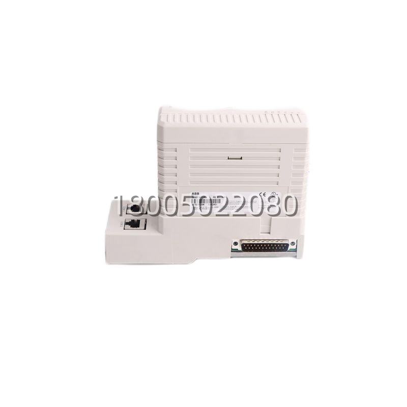
Technical Specifications
| Parameter Name | Parameter Value |
|---|---|
| Product Model | PFEA112-20 |
| Article Number | 3BSE050091R20 |
| Manufacturer | ABB (Drives / Motion) |
| Product Type | Tension Electronics Unit, Dual-Zone |
| Compatible Drives | ABB ACS800 (via NDCU-04 AOC2/AMI2), ABB ACS880 (via AM12 AI), any drive accepting ±10 V / 4–20 mA tension ref |
| Zones | 2 (independent tension PID per zone) |
| Tension Input (per zone) | Strain-gauge load cell, 4-wire, mV signal (excitation supplied by PFEA, typ. 5–10 V DC) |
| Optional Dancer Input (per zone) | ±10 V pot / 4–20 mA (dancer-arm position feed-forward) |
| Tension Output (per zone) | ±10 V (to drive CU analog in), 4–20 mA (recorder/secondary) |
| Break Relay (per zone) | Potential-free NO/NC, ~250 V AC / 2 A (break magnet / mechanical brake) |
| Control Algorithm | Tension PID + dancer feed-forward + acceleration comp (drive-speed feedback via analog/Modbus) |
| Communication | Modbus RTU (standard on -20; -60 variant adds Profibus DP) |
| Supply Voltage | 24 V DC (±10 %), ~5–8 W |
| Mounting | 35 mm DIN rail |
| Commissioning Interface | Front numeric LCD + keypad (zero, span, Kp/Ti/Td, break delay, watchdog) |
| Indicators | PWR, RUN, Zone1/Zone2 Fault, Break-Relay status |
| Operating Temp. | 0 … +50 °C |
| Protection | IP20 (cabinet internal) |
| Sibling Variants | PFEA111-20 (single-zone), PFEA113-20 (triple-zone), PFEA112-60 (dual + Profibus DP) |
| Dimensions (approx.) | ~110 × 130 × 75 mm (W×H×D, DIN enclosure class) |
| Weight | ~0.4–0.6 kg |
Main Features and Advantages
Dual Independent Tension Zones in One DIN Unit. The PFEA112-20 is the dual-zone member of the PFEA family — one unit covers, for example, an unwind zone + winder zone on a single-machine converting line, or a nip-feed zone + winder zone on a small paper-machine reel-up, or a bridle-1 zone + bridle-2 zone on a strip-processing line. Each zone has its own load-cell input (4-wire strain gauge, mV), its own PID block (Kp/Ti/Td tunable from the front keypad or via Modbus RTU), its own ±10 V output to the drive CU, and its own break-relay. This “two zones, one box” beats buying two PFEA111-20s (single-zone) — saves DIN width, saves a 24 V feed, and the PFEA112-20‘s Modbus RTU can report both zones’ tension-actual, PID output, break-relay state, and fault bitmap to the plant PLC/SCADA in one telegram. For a 6-stand tandem mill’s winder section (unwind + rewind = 2 zones), one PFEA112-20 + two ACS800 inverter books (NDCU-04 each) is a clean BOM.Built-In Load-Cell Amplification & Excitation. The PFEA112-20 supplies the 5–10 V DC excitation to the load cells (4-wire: +exc, –exc, +sig, –sig) and amplifies the microvolt-to-millivolt strain-gauge signal to an internal digital tension value — no external load-cell amp / transmitter needed. This is a big deal because load-cell signals in a winder MCC are notoriously noisy (the drive’s 690 V switching, the motor cables, the brake resistor chopper) — the PFEA112-20‘s amplification stage is screened for the drive-MCC environment, and the front-panel zero/span routine walks the tech through “no web → zero → hang known 100 kg weight → span” in 3 minutes. The alternative — a generic 4–20 mA load-cell transmitter sitting in the roll-housing (hot, vibrating, humid) — drifts in 6 months; the PFEA112-20 sits in the cool MCC panel, and the 4-wire load-cell cable is the only thing in the hot zone. Shield discipline: the load-cell cable must be shielded twisted pair, drain landed at the PFEA112-20 end only (MCC star), not at the load-cell end (which is often grounded to the machine frame already) — the PFEA112-20‘s excitation/common is isolated, so ground-loop across a 30 m load-cell run shows up as tension-PV wandering ±2 % at the drive scan, which the winder cascade amplifies into visible reel-taper defects on a paper-machine reel.Dancer/Pot Feed-Forward per Zone. Each zone on the PFEA112-20 has an auxiliary ±10 V / 4–20 mA input intended for a dancer-arm position transducer (potentiometer or 4–20 mA linear transducer). The dancer signal feeds feed-forward into the tension PID: when the dancer moves (web-acceleration, roll-diameter change, splice bump), the PFEA112-20 anticipates the tension excursion and biases the PID output before the tension error itself grows. On a high-speed film winder (800–1200 m/min) or a paper-machine winder (1500–2000 m/min), dancer feed-forward is the difference between a tight reel and a collapsed core. The PFEA112-20 also accepts drive-speed feedback (via an analog input from the drive’s speed-actual AO, or via Modbus from the drive CU) to compute acceleration-compensation — as the winder diameter grows (unwind) or shrinks (winder), the motor speed changes even at constant tension, and the PFEA112-20 adjusts the PID bias accordingly so the ±10 V ref to the drive CU doesn’t have to chase diameter math.Break-Control Relay per Zone. Each zone has a potential-free NO/NC relay (rated ~250 V AC / 2 A) intended for the zone’s mechanical break / unwind-brake magnet. The PFEA112-20 drops the break-relay (opens NC, closes NO) when: (a) tension is lost (load-cell fault, web break detected by tension-drop below threshold for >X ms), (b) the PFEA112-20 itself faults (PWR loss, PID math error, watchdog from plant PLC missing), or (c) a manual “E-STOP winder” is asserted via the PFEA112-20‘s digital input (if wired). This break-relay logic is safety-consequential: on an unwind zone, if the web breaks and the unwind motor keeps spinning (torque ref still alive from the drive CU because the PFEA112-20 didn’t drop the break), the unwind roll can over-speed and disintegrate — the PFEA112-20‘s break-relay + the drive CU’s “zero-speed / web-break” CFC (if the plant also runs winder logic on the CU) form a two-layer guard. The break-relay also has an adjustable delay (parameter on the PFEA112-20 keypad) so a momentary tension dip (splice bump) doesn’t drop the break and shock the web.Front LCD + Keypad Commissioning, Modbus RTU Supervisory. The PFEA112-20 doesn’t need a laptop to commission — front numeric LCD shows tension-actual per zone (kg/N), PID output (%), break-relay state, fault code; keypad has Zero, Span, Up/Down, Enter, Mode. A winder tech can zero both load cells (web lifted off rolls), hang a known 50 kg calibration weight on the web (or use the roll’s known tare + web linear density × span-length), punch in the span value, and the PFEA112-20 computes the mV/kg gain. Then tune Kp/Ti/Td while the line runs at 30 % speed — no PG, no software, 10 minutes. For the plant, Modbus RTU (RS-485, 19.2–187.5 kb/s) lets the S+ node (HPC800 + PDP800) or the AC 800M or even an S7-400 pull tension-actual, PID output, break-relay status, and fault bitmap every 100 ms — so the DCS can log “winder zone 2 tension excursion at 14:32:07” and correlate to the splice event. The -20 variant keeps Modbus RTU; if the plant DCS is Profibus-only, they’d spec PFEA112-60 instead (Profibus DP V1, same dual-zone hardware, different comms piggyback) — but many plants keep -20 + a small Modbus→Profibus gateway if they must, because the -20 is more available in spares channels.Watchdog & Plant PLC Integration. The PFEA112-20 has a watchdog input (Modbus RTU or a dry-contact from the plant PLC/SCADA) — if the plant doesn’t toggle the watchdog within the timeout (e.g., 500 ms), the PFEA112-20 faults both zones, drops both break-relays, and drives the ±10 V outputs to 0 V (or to a configurable safe state — some plants configure “drive CU sees 0 V = zero torque ref” via the CU’s analog-input fault-config). This lets the plant DCS (S+ / AC 800M / S7-400) supervise the winder: if the DCS crashes or the Modbus RTU link drops, the winder doesn’t keep running blind — it faults safe. The watchdog is the “soft tie” between the PFEA112-20 and the plant; the hard tie is the ±10 V to the drive CU (which the DCS also supervises at the drive level via PDP800 or NETH-21).