WhatsApp:+86 18005022363 WeChat: +86 18005022363
  Email:
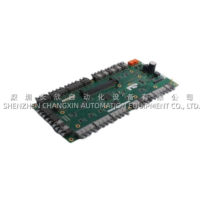
Technical Specifications
| Parameter Name | Parameter Value |
|---|---|
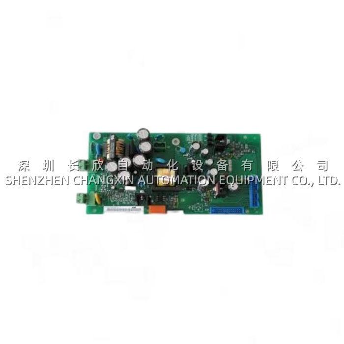
| Product Model | 3BHE024855R0103 (AIN – Analog Input, Rev 0103) |
| Manufacturer | ABB (Excitation / Power Grids) |
| Product Type | Analog Input Module (Excitation System AIN) |
| Platform | ABB UNITROL 6000 / UNITROL 5000 Excitation System |
| Channels | Multi-channel (typical Unitrol AIN: 6–10 inputs covering Gen V, Gen I, Bus V, Field I, auxiliary) |
| AC Input (VT-derived) | 110 V / √3 or 110 V L-L nominal (generator VT secondary), 50 Hz / 60 Hz |
| DC Input (Shunt) | 60–75 mV nominal (field-shunt), ±range per config |
| CT Input | 1 A / 5 A nominal (generator CT secondary), burden ≤ 0.2 VA |
| Filtering | Hardware antialiasing + 80 Hz (50 Hz sys) / 96 Hz (60 Hz sys) notch for rectifier 2nd harmonic |
| A/D Conversion | 12–16 bit class (Unitrol generation-dependent) |
| Accuracy | ±0.2% full-scale typical (after calibration), ±0.1% achievable on VT-path |
| Interface to COB | Unitrol backplane (parallel / proprietary bus to 3BHE013868 COB) |
| Connectivity | Front terminal block (VT/CT/shunt wires) + backplane header |
| Power | From Unitrol rack backplane (typically 5 V DC / ±15 V from rack PSU) |
| Mounting | Unitrol rack slot (DIN-rail inside excitation cubicle) |
| Operating Temperature | –10°C to +55°C (excitation cubicle ambient) |
| Storage Temperature | –40°C to +70°C |
| Humidity | 5%–95% RH, non-condensing |
| Protection | Conformal-coated PCB, IP20 (cabinet-only) |
| Dimensions (approx.) | ~160 × 100 × 30 mm (Unitrol rack module size) |
| Weight | ~0.25–0.4 kg |
Main Features and Advantages
Multi-signal acquisition in one slim module. The 3BHE024855R0103 consolidates what a generator AVR needs: 3× phase-to-neutral VT (generator terminal voltage, used by the AVR’s voltage-regulation loop), 3× phase CT (generator current, used for var calculation, PSS, and current-limiter logic), 1× bus VT (infinite-bus reference for synch/PF control), 1× field-shunt mV (actual field current, used by the AVR’s inner current loop and OXL/UEL limiters), and often 1–2 auxiliary analog (PF transducer, station-bus V, etc.). Doing this in one 3BHE024855R0103 instead of six separate transmitters saves panel space, eliminates 4–20 mA wiring, and — crucially — keeps all signals sampled synchronously on the same A/D clock, so the AVR’s V-I vector (used for PF/var and PSS) has no inter-channel skew. On a 500 MVA thermal unit, that skew matters for PSS phase compensation.Hardware notch filtering for rectifier 2nd harmonic. A unit-connected generator’s terminal voltage isn’t clean sine — the generator’s own excitation rectifier (6-pulse or 12-pulse) injects a 2nd harmonic (100 Hz on 50 Hz grid, 120 Hz on 60 Hz) onto the VT waveform. If the AIN board passed that unchecked to the AVR, the voltage-regulation loop would see a 100 Hz ripple and could oscillate or over-modulate. The 3BHE024855R0103 builds in a 80 Hz (50 Hz system) or 96 Hz (60 Hz system) twin-T or digital notch in the hardware front-end, killing the 2nd harmonic before the A/D samples it. This is why ABB Unitrol holds <0.5% voltage regulation steady-state on 12-pulse thyristor exciters — the 3BHE024855R0103 cleans the V-sense before the COB ever sees it.Scaled ranges per input type. The 3BHE024855R0103 doesn’t treat all channels alike: VT channels are scaled for 110 V / √3 (or 110 V L-L) AC, CT channels for 1 A / 5 A AC with burden matching the CT’s 5 VA / 10 VA class, and field-shunt channels for 60 mV / 75 mV DC (the shunt is typically 60 mV @ rated field current, e.g., 2500 A → 60 mV shunt = 0.024 Ω). The A/D’s gain and the COB’s software gain are matched to these ranges — swapping a 3BHE024855R0103 R0103 into a rack expecting the older R0001 may require a COB parameter re-load (gain/bias per channel) if ABB changed the onboard resistor divider ratio between revisions. This is why “R0103” matters — it’s not just a cosmetic suffix.Backplane integration with COB and DIO. The 3BHE024855R0103 slots into the Unitrol rack’s backplane alongside the COB (3BHE013868), the DIO (3BHE014067, digital I/O — start/stop, contactor control, alarm relays), and the PCD (3BHE013867, pulse-crowbar-diode for thyristor firing). The AIN’s digitised samples land on the backplane every ~1–2 ms (Unitrol scan rate), and the COB’s AVR + PSS + limiter blocks consume them the next scan. If the 3BHE024855R0103 develops a stuck channel (e.g., Gen V Phase A reads 0 V while B and C read normal), the COB’s “VT Fuse Fail” or “VT Discrepancy” logic catches it (3-phase sum check: Va+Vb+Vc ≈ 0 for healthy 3× VT) and falls back to V-Reg on the remaining two phases or transitions to Manual (field-current) regulation — the unit stays online, which is the whole point of redundant sensing.
Application Field
The 3BHE024855R0103 is deployed wherever ABB Unitrol excitation is the AVR — which is a long list across generation. A 660 MW coal-fired unit with a UNITROL 6000 on the turbine-generator (static thyristor exciter, 6-pulse, 415 V AC field supply stepped up via exciter transformer): the 3BHE024855R0103 lands the generator VT (3× 110 V / √3 from 11 kV PTs), generator CT (3× 1 A from 25 kA CTs), bus VT (infinite-bus 110 V), and field shunt (60 mV @ 2400 A field). During a grid disturbance (e.g., a 230 kV line trip 40 km upstream causing the generator to accelerate 0.8 Hz for 300 ms), the AVR needs clean, low-latency V and I to compute the PSS delta-omega and delta-P injection — the 3BHE024855R0103‘s 80 Hz notch + 1–2 ms scan is what lets the PSS damp the inter-area mode instead of exciting it. If the AIN’s CT channel A drifts +3% (CT secondary terminal oxidation at the AIN’s front block), the PSS sees a fake “Ia ≠ Ib=Ic” asymmetry, injects a wrong phase into the firing angle, and the unit may oscillate at 0.3 Hz for an hour before the EE figures it out. The fix: swap the 3BHE024855R0103, reload the COB config (gain/bias per channel, pulled from the Unitrol backup file), and the PSS stabilises.In hydro (run-of-river Francis, 50–200 MVA), the Unitrol often sits in a vibration-heavy penstock-deck cubicle — the 3BHE024855R0103‘s front terminal-block screws (M3, 0.5 N·m) walk loose over 3–5 years from the turbine’s 1.4× runner-frequency vibration (Francis: ~2.5–4 Hz blade-pass, harmonics into the cubicle slab). The symptom: intermittent “Gen V Phase B Loss” alarms every few weeks, always during high-load (turbine at full wicket-gate, vibration peaks). The fix: re-torque the AIN’s VT terminals during the annual outage + apply a dab of thread-locker. If the AIN itself is aged (op-amp drift >0.3%), swap the 3BHE024855R0103 — one spare per hydro unit is standard (most hydro plants run 2–6 units, so 2–6 spares plant-wide).In nuclear (turbine-generator excitation retrofit — many plants retrofitted rotating exciters to static thyristor with Unitrol 6000 in the 2005–2012 window), the 3BHE024855R0103 is in a Seismic-Qualified / Q-class cubicle. The AIN’s conformal coating and backplane keying matter more here — a loose AIN in a seismic event could walk out of the backplane (unlikely but surveyed). Nuclear spares strategy: 1 cold-spare 3BHE024855R0103 per 2-unit bay, stored in the protected store (not the local cubicle — radiation/heat ages electronics faster inside the cubicle during refuel outages when the vent is off).Retrofit / life-extension: plants with Unitrol 6000 commissioned 2006–2012 are now seeing first 3BHE024855R0103 failures — not the dividers (stable), but the A/D hybrid and the op-amp front-end. A plant may proactively replace all AIN boards in a 4-unit bay during a refuel outage — 4 × 3BHE024855R0103 — because opening the excitation cubicle (Category: “Safety-Related” in nuclear, “Critical” in thermal) requires work-permit, LOTO on the exciter DC field breaker, and coordination with the unit operator. Doing it once per 5 years is cheaper than 4× scattered outages. Specialist-surplus with a calibration check (VT-sim 0–120 V AC, CT-sim 0–5 A, shunt-sim 0–75 mV DC, all three checked against expected A/D counts) is the usual source — ABB’s new lead on 3BHE Unitrol spares in this tier is 12–20 weeks, and a 500 MW unit down waiting on a courier for an AIN is ~€300k/day lost infeed.
Related Products
- 3BHE013868R0002 (COB – Controller Output Board): The Unitrol “brain” the 3BHE024855R0103 feeds; AVR + PSS + limiter logic lives here. Keep one cold-spare COB per bay.
- 3BHE014067R0002 (DIO – Digital I/O): Digital sibling in the Unitrol rack — start/stop, contactor close/open, alarm relays, manual/auto switch. Shares the backplane with 3BHE024855R0103.
- 3BHE013867R0002 (PCD – Pulse/Crowbar/Diode): Thyristor firing interface; the COB’s firing-angle output goes to PCD, which drives the exciter thyristors. Related failure mode if AIN under-reads field current (COB over-fires to compensate, PCD sees overcurrent).
- 3BHE014050R0002 (AIN – earlier rev): Predecessor AIN to the 3BHE024855R0103; if your rack has 014050, the 024855 R0103 may be backward-compatible with COB firmware update — verify before swapping (ABB publishes interop notes Unitrol 6000 Spare Cross-Ref).
- Unitrol Rack PSU (5 V / ±15 V): Feeds the 3BHE024855R0103 and COB/DIO/PCD; if the PSU sags, the AIN’s A/D reference drifts — check PSU before condemning AIN.
- Generator VT / CT / Field Shunt (primary transducers): The 3BHE024855R0103 only sees secondaries (110 V, 1 A, 60 mV) — if the primary VT/CT drifts, the AIN reads “wrong” but isn’t faulty. Rule out primaries first.
- ABB Unitrol 6800 / 6200 (newer excitation): If the Unitrol 6000 rack is end-of-life, the 3BHE024855R0103 has no direct sibling in 6800 (6800 uses different backplane / S800 I/O + PM8xx) — migration audit needed if retiring Unitrol 6000.
📌 BOM caution: “3BHE024855R0103” = AIN Rev 0103. Earlier racks may have R0001 or R0101 — the channel count, divider ratios, and backplane connector pinout can differ by one position between R0001 → R0103 (ABB respun for component obsolescence, e.g., op-amp changed from LT1013 to AD8676, gain resistor changed 0.1%). A 3BHE024855R0103 in an R0001 rack may fit mechanically, but the COB’s AIN gain/bias parameters (loaded from the Unitrol backup
.parfile) expect the R0001 ratio — mismatch shows up as “Gen V reads 105% when it’s 100%” or “Field I reads 98% when it’s 100%,” which makes the AVR hunt ±0.3 kV. Always send a photo of the existing AIN label + the COB faceplate + the Unitrol rack nameplate before ordering.
Installation and Maintenance
Pre-installation preparation: Before replacing a 3BHE024855R0103 in a Unitrol rack, coordinate a unit “Excitation Out of Service” permit — the generator must be off-line (or at minimum, the AVR switched to Manual / Field-Current regulation with the turbine at part-load, because losing the AIN mid-operation means the COB loses Gen V/I sense and will either trip “VT Loss + Manual Fallback” or — worse on misconfigured units — over-fire the field trying to “find” the voltage). Lock out the exciter DC field breaker, discharge the exciter DC side (the field circuit stores energy in the field winding inductance — the Unitrol has a discharge resistor, wait the published 30-sec minimum + verify 0 V DC at the field terminal with a DVOM before touching). Open the Unitrol rack front panel, locate the AIN — typically adjacent to the COB on the backplane, identifiable by 3× VT wires (red/yellow/blue, 2.5 mm²) + 3× CT wires (black, 2.5 mm²) + 2× shunt wires (mV pair, often shielded twisted pair) landing on the front terminal block. Photo the terminal positions and the backplane header orientation before extraction — the 3BHE024855R0103 is keyed but the backplane header polarization (pin 1 marker on the ribbon vs. pin 1 on the board silkscreen) matters. Unscrew the front terminals (M3, 0.5 N·m, small blade — over-torque lifts the PCB pad), unplug the backplane ribbon, release the DIN / rack clip, extract. Seat the new 3BHE024855R0103: DIN clip, backplane ribbon (pin 1 → pin 1, red stripe on ribbon = pin 1), front terminals — VT: 3× phase to the AIN’s VT terminals (markings: V1, V2, V3 or A-B-C per Unitrol wiring diag), CT: 3× phase to CT terminals (K/L polarity matters — CT secondary must be wired K→AIN, L→AIN with L grounded at the CT marshalling, not at the AIN — standard VT/CT secondary grounding discipline), shunt: +shunt → AIN “+mV”, –shunt → AIN “–mV” (polarity matters: reversed shunt reads negative field current, COB thinks “field negative” and over-fires). Torque front terminals to 0.5 N·m. Close rack, remove LOTO, power up Unitrol (rack PSU first, then COB boots). The COB will run a self-check — watch the Unitrol local HMI (or ABB Drive Composer / Unitrol PC tool): the AIN channels should read Gen V ≈ 110/√3 V (if VT secondaries present — on a de-energized generator, you’ll read 0 V, which is correct; to test live, need generator rolling at kV). If the COB flags “AIN Channel Discrepancy” or “VT Fuse Fail” on first boot with the new 3BHE024855R0103, check: (a) backplane ribbon pinned correctly, (b) VT/CT/shunt terminals not swapped (common: shunt mV lands on VT terminal — AIN sees 60 mV on a 110 V range, reads ~0 V, COB flags VT Loss), (c) COB parameter set — if swapping R0001 → R0103, reload the AIN gain/bias from the backup .par (ABB Unitrol PC tool: “Download Parameters”) — the new AIN’s divider ratio may differ by 0.5–1%, and the COB needs the corrected gain.