WhatsApp:+86 18005022363 WeChat: +86 18005022363
  Email:
Application Scenarios:
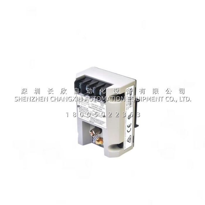
An OEM builds centrifugal air compressors and ships them worldwide. Each machine leaves the factory with a control panel that already reads pressure, temperature, flow and motor current. The customer now asks a question that sounds simple and is not: “can you give us a vibration signal too?”The options are unattractive. A full machinery monitor rack costs more than the margin on a small compressor, needs panel space that does not exist, and requires configuration expertise the OEM’s panel shop does not have. A velocity sensor bolted to the casing is cheaper but reads casing motion, which on a machine with a stiff bearing housing tells you very little about what the rotor is actually doing. And the probe installation space inside the machine is measured in millimetres.This is the gap the 990-05-70-01-01 was designed to fill. Paired with a 3300 NSv narrow-side-view probe — small enough to fit where a standard probe will not — it delivers a single 4–20 mA signal that drops straight into an existing analog input card. No rack, no monitor configuration software, no vibration specialist on staff. The panel shop wires it like any other two-wire transmitter, and the machine ships with a vibration trend the end user can alarm on.The second pain point shows up on the maintenance side, and it is a subtle one. A vibration transmitter is not a monitoring system: it does not capture waveforms, it does not tell you whether the problem is unbalance, misalignment or a cracked rotor, and in the event of an alarm the dynamic data that would explain the trip was never recorded. Bently Nevada states this limitation plainly in the datasheet. The 990-05-70-01-01 is genuinely good at what it does — measuring overall vibration level and trending it reliably — and plants that understand that boundary get excellent value from it. Plants that expect it to diagnose a fault will be disappointed. The honest framing is: this is the right device for trending and alarm on general machinery, and the wrong device as a substitute for a continuous monitoring system on a critical machine.
Parameter:
| Main Parameters | Value/Description |
|---|---|
| Product Model | 990-05-70-01-01 — 990 platform, 0–5 mils pp range, 7 m system, DIN-rail mount, CSA Div 2 |
| Manufacturer | Bently Nevada (Baker Hughes) |
| Product Category | Two-wire, loop-powered vibration transmitter (4–20 mA signal conditioner) |
| Measurement Type | Relative shaft vibration, peak-to-peak displacement — measured via eddy-current proximity probe, not casing velocity |
| Full-Scale Range | Option 05: 0–5 mils peak-to-peak (0–125 μm pp); other available options include 0–4, 0–8 and 0–10 mils pp |
| Input | Accepts one non-contacting 3300 NSv proximity probe with matching extension cable; integrated Proximitor* sensor, no external conditioning unit required |
| System Length | Option 70: 7.0 metres (23.0 feet) calibrated probe + extension cable system (5.0 m also available) |
| Output Signal | 4–20 mA DC, two-wire loop-powered, proportional to peak-to-peak vibration over the specified full-scale range |
| Loop Accuracy | Within ±1.5 % over the specified full-scale range (rated from the TEST signal input to the voltage across a 250 Ω loop resistance) |
| Power Requirement | +12 to +35 V DC at the transmitter terminals; a 28 V supply is typical for Zone 2 / Division 2 installations |
| Maximum Loop Resistance | 1,000 Ω including cable resistance, at 35 V DC |
| Current Limiting | 23 mA typical — protects the receiving input card during over-range conditions |
| Frequency Response | 5 Hz to 6,000 Hz (+0, −3 dB) — covers running speed and the blade-pass and gear-mesh frequencies that matter on most general machinery |
| Probe Gap Range | 0.5 mm to 1.75 mm (20 to 55 mils) from the target surface, required to hold the full-scale linear range |
| Minimum Target Size | 9.5 mm (0.375 in) diameter |
| Not OK / Signal Defeat | Output forced below 3.6 mA within 100 µs of a detected probe or connection fault; restores 2–3 seconds after the fault clears |
| Power-Up Inhibit | Output held below 3.6 mA for 2–3 seconds after power application, suppressing false alarms during startup transients |
| Diagnostics Output | Non-isolated “PROX OUT” and “COM” terminals plus a coaxial connector providing dynamic vibration and gap voltage for external analysers (maximum 3 m lead length) |
| Calibration | Non-interacting external zero and span potentiometers located under the transmitter label; a Test Input pin allows loop verification with a function generator |
| Mounting | Option 01: 35 mm DIN-rail clips (bulkhead screws and a combined clips-plus-screws option are also available in the series) |
| Environmental Adaptability | Transmitter operating −35 °C to +85 °C; probe operating −52 °C to +177 °C; storage −52 °C to +100 °C; 100 % condensing humidity, non-submerged, with coaxial connectors protected; potted construction |
| Agency Approval | Option 01: CSA Division 2 (other option codes cover ATEX Zone 0/2 with ABS maritime, and country-specific approvals) |
| Mechanical / Weight | Approx. 100.1 × 73.9 × 53.3 mm housing; transmitter weight 0.43 kg (0.9 lb); total system weight approx. 0.82 kg |
| Origin | United States |