WhatsApp:+86 18005022363 WeChat: +86 18005022363
  Email:
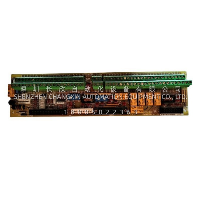
Product Overview
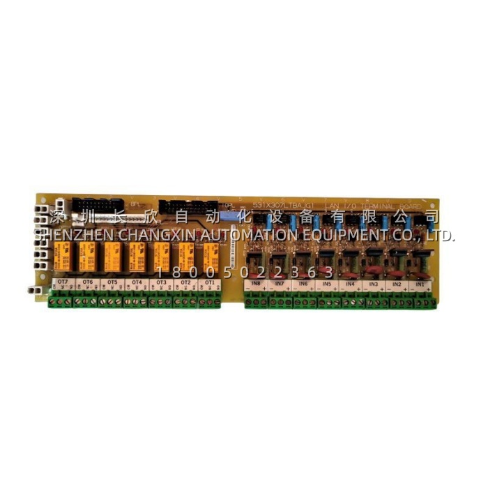
The GE 531X305NTBANG1 is an NTB/3TB terminal board from GE’s 531X family of drive and excitation replacement boards. Physically it lives inside the drive or exciter cabinet, and functionally it is the single point where the control core meets the outside world: the board carries passive interface circuitry plus the terminal strip — board 3TB — that provides connection points for most of the drive’s external signal-level I/O. Rather than performing control computation itself, the 531X305NTBANG1 conditions, distributes and terminates the signals and supplies that the rest of the system depends on, which is why it is often described as the interface backbone of the cabinet.In the system architecture, the 531X305NTBANG1 connects upstream to the drive control board through plugs 6PL and 8PL, to the power supply board through plugs 2PL and 4PL, and outward to field equipment through plug COMPL and the 3TB terminal strip. Across that boundary it provides a remarkably complete set of services: regulated 5 V DC and 15 V DC supplies and unregulated 24 V DC or 125 V AC outputs for powering encoders, sensors and pilot devices; a differential A-quad-B encoder interface with marker channel that is optically isolated on the drive control board and jumper-selectable for 5 V or 15 V encoders; seven relay outputs configurable as Form A or Form C with contacts rated for 120 V AC; low-level analogue inputs and outputs with coarse scaling through DIP switches and fine scaling through four on-board potentiometers; analogue tachometer and reference inputs; digital control inputs; and RS-232C and RS-422 serial interfaces.Because it concentrates so many functions on one assembly, the GE 531X305NTBANG1 is a familiar item in excitation racks, DC and AC drive retrofits and turbine control cabinets. It is documented in GE instruction manual GEI-100020B, is supplied at revision N in board group G1, and is now a discontinued service part, which makes verified stock and correct revision matching the two factors that determine whether a replacement restores the cabinet quickly.
Technical Specifications
| Parameter Name | Parameter Value |
|---|---|
| Product Model | 531X305NTBANG1 |
| Manufacturer | General Electric (GE Motors and Industrial Systems) |
| Product Type | NTB/3TB Terminal Board (Drive / Exciter Terminal Board) |
| Series / Platform | GE 531X series; EX2000 / EX2100 excitation systems, AC/DC2000 drive family |
| Alternate Part Number | F31X305NTBANG1 (functionally equivalent designation) |
| Instruction Manual | GEI-100020B (supersedes GEI-100020A) |
| Revision / Board Group | Revision N, Board Group G1 |
| Regulated Power Outputs | +5 V DC and ±15 V DC, 300 mA each |
| Unregulated Power Outputs | ±24 V DC, 500 mA; 120 V AC, 0.5 A (125 V AC input variant) |
| Encoder Interface | Differential A-quad-B with marker channel, jumper-selectable 5 V or 15 V encoder supply |
| Analog Tach Input Scaling | 25 V to 380 V (6 V to 65 V with drive control board jumper JP7 in position 2-3) |
| Analog Reference Scaling | 9 V to 29 V |
| Coarse Scaling Method | DIP switches SW1 through SW7 |
| Fine Scaling Method | Four on-board potentiometers for low-level analogue I/O |
| Relay Outputs | 7 total, configurable as Form A or Form C |
| Relay Contact Rating | 120 V AC, 0.5 A general-purpose; MA pilot relay contacts 125 V AC, 2 A |
| Digital Control Inputs | Up to 12 general-purpose inputs (up to 24 V DC) plus dedicated RESET and CONTROL ON |
| Serial Interfaces | RS-232C and RS-422, with termination resistors JP1 / JP2 for RS-422 |
| Test Points | Multiple on-board testpoints including ±10 V DC analogue outputs corresponding to 3TB pins 53, 54, 55 |
| Relay Component Type | DS2E-M DC24V H300 (6 left-side, 1 right-edge) |
| Board Components | 7 toggle switches, 4 potentiometers, 2 inductor coils, 24 jumper switches, 6 terminal strips, 3 vertical pin cable connectors |
| Power Consumption | 100 mA @ 5 V DC / 120 mA @ 24 V DC |
| Operating Temperature | 0 °C to +60 °C (industrial grade) |
| Storage Temperature | -40 °C to +85 °C |
| Relative Humidity | 5 % to 95 % RH, non-condensing |
| Mounting | Cabinet / backplane installation in 531X series position |
| Country of Origin | United States |
| Approximate Weight | 0.44 kg to 0.5 kg |
| Lifecycle Status | Discontinued by the manufacturer; supplied from verified stock or refurbished inventory |
Main Features and Advantages
Power distribution built into the terminal layer: The 531X305NTBANG1 generates both regulated and unregulated supplies at the point where field devices are actually terminated. Regulated +5 V DC and ±15 V DC at 300 mA feed encoders and sensitive transducer electronics, while unregulated ±24 V DC at 500 mA and a 120 V AC output at 0.5 A cover pilot devices, interposing relays and indication circuits. This removes the need for a separate distribution terminal block and the extra wiring, cost and failure points it would introduce.Encoder interface that adapts in the field: Speed and position feedback is handled by a differential A-quad-B interface with a marker channel, optically isolated on the drive control board for noise immunity in high-power cabinets. Because the encoder supply is jumper-selectable between 5 V and 15 V, the 531X305NTBANG1 can be matched to whatever feedback device is installed without changing hardware or rewiring, which matters greatly during retrofits where the mechanical encoder is often retained.Relay outputs without interposing hardware: Seven relay outputs, each configurable as Form A or Form C and rated for 120 V AC, give the board direct authority over contactors, annunciators, solenoid valves and interlock circuits. Contacts derived from the MA contactor pilot relay are separately rated at 125 V AC, 2 A. The practical benefit is that most annunciation and interlocking requirements are satisfied on the board itself rather than through an external relay rack.Analogue scaling that can be trimmed on site: Coarse range selection for analogue tachometer and reference signals is made through DIP switches SW1 to SW7, covering tach inputs from 25 V to 380 V and references from 9 V to 29 V, while four on-board potentiometers handle fine scaling of low-level analogue I/O. A commissioning engineer can therefore match the board to the actual machine without changing components or ordering a different variant, and can recalibrate after a transducer is replaced.Serial access for commissioning and diagnostics: With RS-232C and RS-422 available on the board, plus termination resistors for the RS-422 link and multiple testpoints that mirror the principal analogue outputs, the 531X305NTBANG1 gives service personnel direct access to the drive or exciter for configuration, monitoring and fault tracing without disturbing the field wiring on the 3TB strip.