WhatsApp:+86 18005022363 WeChat: +86 18005022363
  Email:
Description
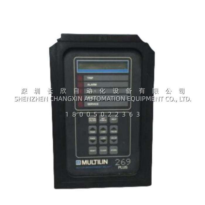
The GE Multilin 269PLUS-100P-120 is a microprocessor-based motor management relay manufactured by GE Multilin (now GE Vernova), designed for the integrated protection, monitoring and control of medium-sized three-phase AC motors. It belongs to the protective relay category, and it consolidates what used to be a panel full of discrete overload relays, RTD monitors, timers and ground-fault devices into a single fixed-mount unit.The relay continuously measures phase and ground current, builds a live thermal model of the motor, reads up to twelve resistance temperature detectors embedded in the windings and bearings, and decides — in milliseconds — whether the motor should keep running, alarm, or trip. Its 100P designation means it is configured for 100 Ω platinum RTDs, and the 120 suffix denotes 120 V AC / 125 V DC control power, the combination most commonly found in North American motor control centres.
Application Scenarios
A municipal water utility runs six vertical turbine pumps on a 4.16 kV medium-voltage bus, each one started a handful of times a day and each one expensive enough that a stator rewind means a six-figure capital request. The problem is never the dramatic failure; it is the quiet one. A pump whose suction screen partially fouls draws a little more current, runs a little hotter, and starts a little more often than the thermal capacity allows — and the existing thermal overload relay, which models the motor from current alone, sees nothing wrong until the winding insulation has already aged past recovery. Installing GE Multilin 269PLUS-100P-120 on that machine changes the picture, because the relay does not infer temperature from current alone: it reads six stator RTDs directly, biases its thermal model with real winding temperature and with negative-sequence current from any phase unbalance, and it remembers thermal history between starts. The pre-trip alarm fires while there is still time to schedule a screen clean instead of a rewind.The second scenario is a refinery compressor where the pain point is operational rather than gradual. Process upsets demand restarts, and restarts are exactly what kills motors: repeated acceleration dumps I²t into the rotor and stator with no time to cool. GE Multilin 269PLUS-100P-120 addresses this with start inhibit and auto-timed lock-out driven by its own learned model of how much thermal capacity a start actually consumes, alongside a supervised emergency restart function for those occasions when production or safety genuinely requires overriding the lockout. The maintenance team gets protection that is neither blindly permissive nor pointlessly obstructive.In both environments the relay solves the same underlying set of problems: motors are protected by inference instead of measurement, failures are discovered after damage rather than before, and there is no record of what actually happened on the last trip.
Parameter
| Main Parameters | Value/Description |
|---|---|
| Product Model | 269PLUS-100P-120 |
| Manufacturer | GE Multilin / GE Vernova (formerly GE Power Management, Markham, Ontario) |
| Product Category | Motor management relay / digital motor protection relay, fixed (non-drawout) mount |
| Model Code Meaning | 269PLUS = series platform; 100P = 100 Ω platinum RTD input; 120 = 120 V AC control power (also accepts 125 V DC) |
| Control Power | 120 V AC / 125 V DC nominal; wide operating band approx. 80–150 V AC/DC; 100 ms ride-through on power loss |
| Power Consumption | 10 VA nominal, 20 VA maximum |
| Phase Current Input | Three-phase CT inputs, 1 A or 5 A secondary selectable; true-RMS measurement, approx. 32 samples per cycle |
| Ground Fault Input | Dedicated ground CT (zero-sequence or residual connection); sensitive earth-fault detection independent of phase CTs |
| RTD Inputs | Up to 12 programmable 100 Ω platinum RTDs — typically RTD 1–6 on stator windings, RTD 7–10 on bearings, ambient and load; per-RTD alarm and trip levels with lead-break detection |
| Digital Inputs | 5 factory-programmed switch inputs (spare input, differential relay contact, speed switch, external reset, emergency restart, access) |
| Output Relays | 4 outputs — 1 latched main trip (86), 1 alarm, 2 programmable auxiliary relays |
| Analog Output | 1 programmable analog output, 4–20 mA or 0–1 mA selectable, assignable to current, thermal capacity, temperature or other measured values |
| Communication | Isolated RS485 port, Modbus RTU protocol; PC configuration and monitoring via EnerVista 269 / 269PC software |
| Protection Functions | Thermal overload (8 standard curves plus user-defined FlexCurve), locked rotor, mechanical jam / rapid trip, short circuit, ground fault, unbalance and single-phasing, undercurrent / load loss, multiple starts, starts-per-hour, stator and bearing overtemperature, emergency restart, variable lock-out time |
| Operator Interface | 48-character alphanumeric backlit LCD with keypad; 5 status LEDs that light to indicate which output operated, with the cause shown on the display |
| Displayed and Logged Data | Actual values, cause of last trip, pre-trip values, thermal capacity used, learned motor data, statistical data and operating hours |
| Operating / Storage Temperature | −25 °C to +60 °C operating; −40 °C to +85 °C storage (some documentation cites −40 °C to +70 °C) |
| Mechanical and Ratings | Panel mount in standard MCC cutout, rugged corrosion- and flame-retardant case with protective cover rated NEMA 12 / IP53; approx. 193 × 125 × 290 mm, approx. 2.8 kg |
| Certifications | UL listed (UL 508 industrial control equipment, UL 1053 ground fault), CSA certified, CE; manufactured under an ISO 9001 registered programme |
| Lifecycle Status | Discontinued by the original manufacturer; available as new surplus and professionally tested replacement stock |