WhatsApp:+86 18005022363 WeChat: +86 18005022363
  Email:
Product Overview
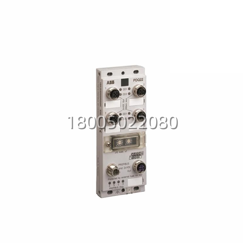
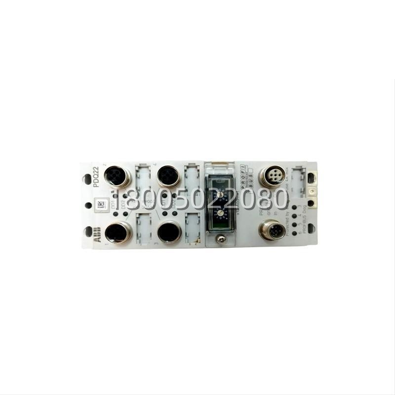
The PDQ22 (order number 1SAJ240200R0050, also referenced as PDQ22-FBP.0) is ABB’s Profibus DP-V0/V1 FieldBusPlug in the Quad configuration — a ready-made Profibus DP interface that lets up to four FBP (FieldBusPlug) terminal devices share a single Profibus DP node on the plant’s Profibus trunk. The FBP architecture is ABB’s Low-Voltage answer to Motor Control Center (MCC) and decentralized motor-starter networking: each intelligent device (UMC22 / UMC22-FBP smart motor controller, AF series FBP-enabled contactors, MMS/MMS100 with FBP adapter, etc.) carries a threaded FBP boss on its front face; the PDQ22 (or its single-device sibling PDP22) screws onto that boss via a bayonet/thread-in action — “click” and it’s seated — and the device’s internal bus (power + data) passes through the PDQ22 to the Profibus network. The “Quad” in PDQ22 means one PDQ22 can aggregate four FBP devices daisy-chained behind it — a 1-to-4 split — so one Profibus DP station address serves four motor starters instead of consuming four addresses. This matters because Profibus DP’s practical node limit per trunk is 32 (without repeater), and a large MCC with 60+ starters would blow past that with single-device plugs — the PDQ22 collapses 4 starters into 1 DP address, freeing headroom.The PDQ22 itself is not a standalone node — it has no station address of its own. The Profibus DP slave identity (DP-V0 cyclic, or DP-V1 acyclic if the host FBP device supports it) lives on the FBP devices behind it; the PDQ22 is the physical/media translator: M12 A-coded 5-pin IN and OUT on the PDQ22 fascia land the Profibus trunk (IN from the upstream repeater/scanner, OUT onward to the next PDQ22 or PDP22 in the “daisy-chain” topology that ABB FBP promotes). Data rate is auto-negotiated up to 12 Mbps. Power is 24 V DC drawn from the host FBP device’s backplane (the UMC22 / AF FBP starter supplies it; typical draw ≤200 mA for the PDQ22 electronics). The head shell is IP65-rated metal (die-cast zinc or aluminum alloy), meaning the PDQ22 survives the MCC environment — oil mist, conductive dust, occasional hose-down near the MCC lineup — while the device behind it (UMC22 in its own IP20/NEMA enclosure inside the MCC drawer) is protected. One diagnostic LED (CM status) on the PDQ22 fascia gives bus-state: green = online, green blinking = data exchange active, red = fault (bus error, GSD mismatch, device not enumerated), off = no 24 V or trunk disconnected.The killer value proposition of the PDQ22 (and FBP architecture generally) is bus-node survival during MCC drawer exchange. In a traditional hard-wired or non-decoupled Profibus MCC, pulling a starter drawer (to replace a burnt contactor or a failed UMC) breaks the Profibus IN→OUT pass-through — the trunk behind that drawer drops, and the DP scanner flags “station lost” for every device downstream. In an FBP MCC, the PDQ22 screws onto the device front, but the Profibus IN/OUT pass-through is physically on the PDQ22 head— when you pull the MCC drawer (UMC22 + starter), the PDQ22 stayson the MCC structure (the FBP boss is on a fixed plate, or the PDQ22 is mounted on a DIN clip that stays with the busbar structure while the drawer slides out — ABB’s FBP mechanicals vary by MCC builder, but the principle holds: the PDQ22 + its M12 IN/OUT tails stay live, the Profibus trunk stays continuous, the DP scanner sees the other three devices behind this PDQ22 (if Quad) and all downstream PDQ22/PDP22 nodes as alive. You swap the UMC drawer, slide the new one in, screw the PDQ22 back onto the new UMC’s FBP boss, and the node re-enumerates — no全线停机. This is why PDQ22 is dense in metals MCCs, crane MCCs, mining conveyor MCCs, and marine switchboards — anywhere a drawer swap shouldn’t kill the bus.
Technical Specifications
| Parameter Name | Parameter Value |
|---|---|
| Product Model | PDQ22 (PDQ22-FBP.0) |
| Manufacturer | ABB (Low Voltage Products – FBP FieldBusPlug series) |
| Order Number | 1SAJ240200R0050 |
| Product Type | FieldBusPlug Quad – Profibus DP-V0/V1 Interface Coupler |
| Protocol | PROFIBUS DP-V0 / DP-V1 (cyclic + acyclic if host FBP device supports DP-V1) |
| Data Rate | 9.6 kbps – 12 Mbps, auto-negotiated |
| Bus Connectors | 2 × M12 A-coded 5-pin (IN / OUT), Profibus standard pinout |
| Channel Capacity | Quad – aggregates up to 4 FBP devices per DP node address |
| Station Addressing | Via host FBP device software (UMC22 parameter / AC500 FBP config); no DIP on PDQ22 |
| Status LED | CM (Communication): green = online, blink = data exchange, red = fault, off = no 24V / trunk disconnected |
| Supply Voltage | 24 V DC (from host FBP device backplane; typical ≤200 mA) |
| Isolation | Bus side to internal ≥500 V DC (per host FBP device spec) |
| Mounting | Thread-in / bayonet onto FBP device front boss; also DIN rail TH35-7.5 / TH35-15 per IEC 60715 (single mounting) |
| Degree of Protection | IP65 (head shell), device-side per host FBP enclosure |
| Dimensions (L × W × H) | 112 mm × 67 mm × 26 mm (package level 1) |
| Net Weight | 443 g |
| Operating Temperature | 0 … +55 °C (MCC cabinet envelope) |
| Storage Temperature | -40 … +85 °C |
| Humidity | 5 … 95 % RH, non-condensing |
| Certifications | CE, cULus, RoHS (no declaration needed per ABB doc) |
| Customs Tariff | 85176200 |
| Container | 1 pc per pack |
Main Features and Advantages
Quad aggregation — one DP address serves four FBP devices. The architectural win of the PDQ22 over its single-device sibling PDP22 is the 1:4 ratio. A bare UMC22-FBP smart motor controller with a PDP22 consumes one Profibus DP station address. Four UMC22s on a PDP22 each = 4 addresses. Four UMC22s behind one PDQ22 = 1 address. On a Profibus trunk limited to 32 nodes (unrepeated), that’s a 4× efficiency gain — a 60-starter MCC that would need two repeaters with PDP22 everywhere can often fit on one trunk with PDQ22 grouping (4 per Quad, 15 Quads = 60 starters, 15 addresses). The DP-V0 cyclic telegram just gets longer (PPO-type scaled) — the scanner sees one slave with, say, 16 input words + 16 output words covering four UMC22s’ status/control, instead of four slaves each with 4/4. For plants standardising on S7-400H PCS 7 or S7-1500 + ET 200 on Profibus, the PDQ22 keeps the IO image tidy.Bus-node decoupling from MCC drawer — the FBP “killer app.” As called out in the Overview, the PDQ22 is the physical enabler of “drawer swap without bus drop.” In traditional MCC Profibus wiring (each starter has a Profibus T-piece landing on DIN-mounted terminals, the T-piece + cable move with the drawer), pulling the drawer disconnects the T-piece, the IN→OUT pass-through breaks, downstream nodes drop. In FBP MCC, the PDQ22 screws onto the UMC22’s FBP boss, but the M12 IN/OUT tails (pre-wired by the MCC builder) land on a fixed DIN clip or on the PDQ22 head which stays with the busbar structure as the drawer slides out — ABB’s FBP mechanicals vary by MCC OEM (ABB MNS, Eaton, Schneider Okken, etc. all license FBP), but the principle is: the PDQ22 + M12 tails stay live, the Profibus trunk continuity is unbroken, the DP scanner sees “station X (the Quad) still alive, devices 2-4 behind it alive, device 1 (the pulled drawer) not responding” — a degraded station, not a lost station. The plant fixes the drawer, slides it back, screws PDQ22 onto new UMC’s boss, station re-enumerates, done — no全线停机, no Profibus re-scanner, no “all motors on this trunk tripped.” In metals rolling MCCs (where a furnace-aux MCC feeds 40+ starters for冷却风机, lubricators, hydraulic pumps) and in crane MCCs (hoist + trolley + gantry + aux on one MCC lineup), this is the difference between a 2-minute drawer swap and a 2-hour bus rebuild.IP65 metal head for MCC-environment survival. The PDQ22 head shell (the part that protrudes from the MCC drawer front, visible to the electrician walking the lineup) is die-cast metal with IP65 rating — oil mist from nearby gearboxes, conductive dust from crusher rooms, salt-air in marine E-rooms, and the occasional hose-down during MCC wash-down all land on the PDQ22 head. The M12 A-coded connectors (Profibus standard: Pin 1=shield, 3=B-data, 4=A-data, 5=+5V? Wait — Profibus over M12 A-coded is typically: Pin 3 = B (Data B, negative), Pin 4 = A (Data A, positive), Pin 5 = shield drain, Pin 1+2 sometimes unused or V+/GND for 24 V — ABB FBP uses M12 A-coded for Profibus, pinout per IEC 61158-2 M12 variant) are screw-locking, not push-pull, so vibration on a mining conveyor MCC or a ship’s switchboard doesn’t work them loose. The 443 g mass is mostly that metal head — it feels substantial in hand, not a plastic toy.Diagnostic CM LED at the MCC front. The single LED on the PDQ22 fascia (labeled CM on ABB docs) is the maintenance tech’s first triage point. Green solid = PDQ22 enumerated on Profibus, DP scanner has this station in “data exchange,” all four FBP devices behind it responsive. Green blinking = data exchange active (blink on each DP cyclic — ~5–20 ms cadence depending on DP speed, so it looks like a fast blink to the eye). Red = fault — could be GSD mismatch (scanner expects DP-V1 acyclic, PDQ22+UMC22 only doing DP-V0; or scanner’s GSD file version doesn’t match the UMC22’s GSD), could be trunk disconnected (IN side M12 loose), could be all four FBP devices behind the Quad dead (rare — more likely one dead, CM stays green because the PDQ22 itself is alive on the bus). Off = no 24 V at the PDQ22 (host UMC22 not powered, or the MCC’s 24 V aux feeder to this drawer tripped). A walk-by tech seeing “CM red” on Quad #3 in Bay B of the MCC knows: check M12 IN on that PDQ22 (loose?), check GSD version in the S7 PG, check if someone powered down that drawer’s 24 V. No laptop needed for first-pass triage.No DIP switches, no firmware — address lives on the FBP device. Like ABB’s other FBP plugs (PDP22 single, PDP12 maybe older gen), the PDQ22 carries zero user-configuration — no Profibus station DIPs, no baud DIPs (auto-negotiate), no firmware to track. The Profibus station address (1–126) is set in the host FBP device — for UMC22-FBP, it’s a parameter in the UMC’s own menu (accessed via the UMC’s local keypad or via the FBP bus from the PLC if DP-V1 acyclic is enabled). The PDQ22 just passes the DP telegram to/from the UMC22’s internal FBP interface. This means a PDQ22 bought today drops onto a 2010-vintage UMC22 and a 2024-vintage UMC22 the same way — same 1SAJ240200R0050, same M12 pinout, same CM LED grammar. The only compatibility watch-out: very early FBP devices (pre-2005 UMC?) might have a different FBP boss thread pitch — ABB standardized FBP boss mid-2000s, and PDQ22 (1SAJ240200R0050) is the current rev, backward-compatible to the FBP-standard bosses. If mixing with very early UMC100 (non-FBP, the older MMS architecture), the PDQ22 won’t fit — those use a different bus (Modbus RTU over terminal, not FBP).GSD file discipline. One operational note that trips first-time FBP deployers: the PDQ22 itself has no GSD — the GSD file is for the FBP device behind it(UMC22-FBP has its own GSD, e.g., ABB_UMC22.gsd or within the ABB FBP GSD collection). When the plant scans Profibus, it sees “ABB UMC22 Quad” (or however the GSD declares the slave), not “PDQ22.” The PDQ22 is invisible to the scanner — it’s the media. So “can’t find station” on first commissioning is almost never the PDQ22 — it’s (a) GSD not imported into STEP 7 / TIA / PCS 7, (b) UMC22 parameter 51.01 (if UMC uses Group 51 analog for FBP) not set to the expected DP-V mode, or (c) M12 IN/OUT reversed (AB: IN = from scanner upstream, OUT = to next Quad/PDP22 downstream — reversing them still passes continuity but the scanner sees “cable break” between this Quad and the next because the OUT is now terminated and the next node’s IN sees nothing). The CM LED helps: CM red + IN M12 loose = reversed or open.