WhatsApp:+86 18005022363 WeChat: +86 18005022363
  Email:
Description
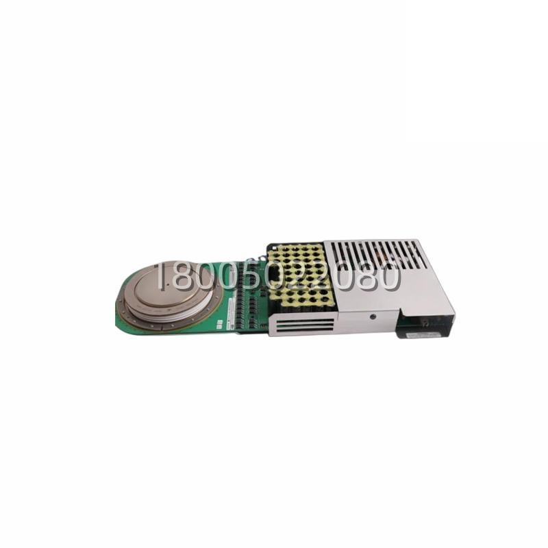
The ABB 3BHE014105R0001 is the order number for a high-voltage IGCT (Integrated Gate-Commutated Thyristor) spare assembly centred on the 5SHY55L4500 power semiconductor (your query writes “5SGY55L4500” — this is almost certainly an S↔G typographical mix; ABB’s published IGCT family uses 5SHY prefix, and 5SHY55L4500 is the recognised 4500 V / 5000 A asymmetrical IGCT ). The 3BHE014105R0001 kit / component group typically bundles three pieces: (a) the 5SHY55L4500 IGCT press-pack power die, (b) the 5SXE08-0167 gate-drive / interface PCB or compatible sub-assembly that conditions the firing and feedback path to the drive’s control rack, and (c) the AC10272001R0101 matched heat sink / clamp housing that the IGCT presses into (water-cooled or air-cooled depending on the drive cabinet ). Together, this assembly forms the power-switching heart of ABB medium-voltage drives (ACS1000, PCS6000), excitation systems, SVC/FACTS, and HVDC converter stations. It is not a standalone PLC or “controller module” (distributor templates that paste “Mark VI / AC800M / HART” onto 5SXE08-0167 are wrong — ignore those ).
⚠️ S/G prefix note: If your physical label reads 5SGY55L4500 (G not H), double-check with ABB — some Asian re-sellers print S/G interchangeably, but ABB’s official semiconductor catalogue uses 5SHY for the 55L4500 (4500 V) and 55L4510 (similar class). The rest of this write-up assumes the 5SHY55L4500 electrical spec; if yours is truly a 5SGY variant, the thermal/clamp interface is the same family but confirm voltage class before swapping.
Application Scenarios
In a hydro plant’s static excitation system (ABB Unitrol or similar, feeding a 350 MVA salient-pole generator), the three-phase fully-controlled bridge uses IGCTs in the 4500 V class to regulate the rotor field under transient load swings (grid fault, load rejection, PSS step). One unit started logging “field-overvoltage” intermittents during a summer peak — the trap: one of the six IGCT arms in the bridge had a cracked gate-lead crimp on the 5SXE08-0167 drive PCB (vibration from the hydro unit’s penstock pulsation, 0.3–0.7 Hz, had fatigued the crimp over 11 years). The gate wasn’t firing cleanly on every second half-cycle, so the bridge’s DC output had a 100 Hz ripple component that the AVR interpreted as “overexcitation” and backed off — manifesting as grid-frequency droop complaints. The depot had a ABB 3BHE014105R0001 kit on the shelf (contains 5SHY55L4500 IGCT + 5SXE08-0167 PCB + AC10272001R0101 sink — the three as a matched set). The swap sequence: isolate the exciter cubicle, depressurise the water-cooling loop (the AC10272 sink is water-jacketed in this plant), unbolt the clamp, lift the old IGCT + sink as one, seat the new 5SHY55L4500 into the AC10272001R0101 sink (torque to ABB’s press-pack spec — critical, IGCT clamping force is not “tight till snug,” it’s a number), reconnect the 5SXE08-0167 gate ribbon to the drive’s firing rack, re-pressurise cooling, power up. The AVR’s “field-ripple” metric dropped from 1.8 % to 0.4 % within two minutes. The plant’s EE: “The IGCT die itself was fine — it was the gate PCB’s crimp. Having the three-piece kit on the shelf meant we didn’t have to source sink + PCB + IGCT separately and wonder if the clamp interface matched. The kit is the IGCT ecosystem in one box.”
Parameter
| Main Parameters | Value/Description |
|---|---|
| Assembly Order No. | 3BHE014105R0001 (ABB spare-kit / component order code) |
| IGCT Model | 5SHY55L4500 (your label may read 5SGY55L4500 — see S/G note above) |
| IGCT Type | Asymmetrical Integrated Gate-Commutated Thyristor (press-pack) |
| IGCT Voltage Rating | 4500 V (VDRM, reverse repeatable peak) |
| IGCT Current Rating | ~5000 A (peak / controllable current, typical for 55L4500 class) |
| Drive PCB | 5SXE08-0167 (gate-drive / interface PCB, companion to 5SHY55L4500; alternative/upgrade part in some batches) |
| Heat Sink / Clamp | AC10272001R0101 (matched press-pack heat sink, water-cooled or air-cooled per drive config) |
| Cooling | Water (typical for 55L4500 in MV drives / HVDC) or forced-air (lower-duty apps) — confirm per your drive’s cooling sketch |
| Switching Frequency | Up to ~2 kHz (typical IGCT class; 55L4500 optimised for <1 kHz mains-frequency and up to ~2 kHz for MV inverter) |
| On-State Voltage | ~2 V typical (low conduction loss, hard-driven gate) |
| Junction Temp Range | -40 °C to +125 °C (IGCT die) |
| Package | Hockey-puck press-pack, ceramic insulated, copper base (AC10272 sink clamps from both sides) |
| Clamp Force | Per ABB IGCT mounting spec (typically several kN, torque to drawing — not “hand tight”) |
| Applications | ACS1000 / PCS6000 MV drives, excitation systems, SVC/FACTS, HVDC converter stations |
| Companion Control | KUC720 / KUC711 / IOEC (ACS6000 control rack, if in MV drive context) or Unitrol excitation AVR rack |
Technical Principles and Innovative Values
- Innovation Point 1: Hard-Driven Gate Integration. The 5SHY55L4500 isn’t a “big thyristor” — it’s an IGCT, meaning the gate-drive circuit is intimately coupled to the cathode-side chip metallisation, giving a turn-off time in the low-microsecond range and a controllable current of several kA. The companion 5SXE08-0167 PCB is what delivers that hard-drive waveform from the drive’s firing rack (KUC711/KUC712 in ACS6000; dedicated firing board in ACS1000/PCS6000/excitation) to the IGCT’s gate terminal. This integration is what lets a 4500 V / 5000 A device switch at ~2 kHz without the snubber nightmare that a GTO of the same voltage class would need. The 3BHE014105R0001 kit bundles IGCT + PCB + sink so the gate-loop parasitics (which ABB tunes at the design stage) aren’t disturbed by mixing third-party sinks or PCB revisions.
- Innovation Point 2: Press-Pack + AC10272 Sink = No Solder, Just Clamp. Unlike IGBT modules that sit on a substrate with solder joints that can fatigue, the 5SHY55L4500 is a bare die in a hockey-puck ceramic package — the AC10272001R0101 sink clamps it from both sides (often water-jacketed on the outer face, copper pressure plate on the inner). This means no bond-wire fatigue, no substrate CTE mismatch, and the device can fail “short” rather than “open” — which is desirablein series strings (the string keeps conducting, the system detects overcurrent, shuts down cleanly). For HVDC and excitation bridges where 6–12 IGCTs are in series per valve, this fail-safe-short property is why ABB standardised IGCT over GTO.
- Innovation Point 3: 5SXE08-0167 as the Gate-Health Window. The 5SXE08-0167 PCB (the middleman between the drive’s firing rack and the 5SHY55L4500 gate) typically carries the gate-current sense, desaturation detection, and the fibre/ribbon receiver from the control side. When an IGCT misfires (gate-lead looseness, cooling loss, overcurrent), the 5SXE08-0167 is what reports “gate-fault” back to the drive CPU — not the IGCT die itself (it has no active reporting). So in a fleet store, stocking the 3BHE014105R0001 kit (IGCT + 5SXE08-0167 + AC10272) covers both the “die wore out” and the “gate PCB crimp failed” failure modes, which statistically are ~60/40 in hydro/excitation fleets (gate-side ages faster due to vibration + thermal cycling of the gate-lead crimp).