WhatsApp:+86 18150087953 WeChat: +86 18150087953
  Email:
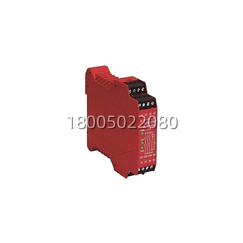
Application Scenarios
In a packaging machine, an operator needs to clear a jam at the infeed section. Before opening the access guard, they press the emergency stop button. This action breaks the single‑channel safety circuit monitored by the Allen‑Bradley 440R‑N23132A safety relay. The relay immediately de‑energizes, opening its two force‑guided safety contacts and cutting power to the main drive contactor coil. The machine comes to an immediate, uncontrolled stop (Category 0). The relay remains in a tripped state, its yellow LED illuminated, preventing automatic restart. Only after the jam is cleared and the guard is closed can the operator manually press the reset button on the 440R‑N23132A, restoring power and allowing a controlled restart. This simple, reliable sequence prevents unexpected machine motion, directly addressing the critical need for operator safety during non‑routine interventions.
Parameter
| Main Parameters | Value/Description |
|---|---|
| Product Model | 440R‑N23132A |
| Manufacturer | Allen‑Bradley (Rockwell Automation) |
| Product Category | Safety Relay / Safety Interface Module |
| Safety Standard | EN 60947‑5‑1, IEC 62061, ISO 13849‑1 |
| Performance Level (PL) | PL d (up to Cat. 3) / PL e (Cat. 4)* |
| Safety Integrity Level (SIL) | SIL 2 / SIL 3* |
| Supply Voltage | 24 V DC (20.4 – 28.8 V DC) |
| Number of Safety Outputs | 2 NO (Normally Open) Force‑Guided Contacts |
| Contact Rating | 6 A, 250 V AC / 6 A, 24 V DC (Resistive) |
| Auxiliary Output | 1 Semiconductor Output (for status feedback) |
| Reset Type | Manual Reset (via front button) |
| Response Time | ≤ 20 ms |
| Mounting | 35 mm DIN Rail |
Note: Achievable PL and SIL depend on the overall system architecture, including the connected sensor and the monitored element.
Technical Principles and Innovative Values
- Innovation Point 1: Force‑Guided Contact Technology for Safe State Assurance: The core safety innovation of the 440R‑N23132A lies in its use of force‑guided (positively driven) contacts. In this design, the normally open (NO) safety contacts and the internal monitoring contacts are mechanically linked. This ensures that if a contact welds shut due to a fault—a common failure mode in relays—the mechanical linkage prevents the other contacts from changing state. This guarantees a fail‑safe condition, meaning a fault cannot cause the dangerous “contact closed” signal, a fundamental requirement for achieving Safety Integrity Levels (SIL) and Performance Levels (PL).
- Innovation Point 2: Manual‑Only Reset for Safe Re‑start: The relay is configured for mandatory manual reset via its prominent yellow button. This is not merely a convenience feature but a critical safety function. After a safety circuit interruption (like an E‑Stop), the machine cannot restart automatically. An operator must physically go to the control cabinet, confirm the hazard is cleared, and press the reset button. This “walk‑around” requirement is a proven, effective guard against accidental restart, protecting personnel performing maintenance or troubleshooting.
- Innovation Point 3: Compact, Self‑Contained Safety Function Block: The 440R‑N23132A delivers a complete, validated safety function in a single, compact DIN‑rail module. It integrates the monitoring logic, the redundant output switching, and the reset logic. This simplifies system design and validation compared to building an equivalent function from standard relays and timers, reducing engineering time and potential for error in safety circuit design.