WhatsApp:+86 18005022363 WeChat: +86 18005022363
  Email:
Application Scenarios
At a 132 kV substation running ABB RET670 bays on the transformer protection panel, the evening operator logged a “CPU Board Fail” alarm on Bay 3, followed quickly by total panel blackout — but the station 24 V DC distribution read a clean 24.3 V at the bay’s PSM output. The protection engineer’s first thought was a dead CPU, which would have meant a full relay change-out and a weekend of CT/VT re-termination. Before pulling the relay, he opened the cubicle door, unlatched the internal module row, and measured the 1MRK002246-BC output pins: +5 V rail reading 0.8 V, +12 V dead, –12 V dead — the primary PSM was fine, but the secondary 1MRK002246-BC that derives logic rails from that 24 V had taken a surge and shut down on OCP. A pre-verified spare 1MRK002246-BC came out of the storeroom, the old board’s ribbon and edge connectors were transferred (the board carries no node-specific calibration — all that lives on the CPU), and ten minutes later the RET670 rebooted clean. The “board-level spare” approach turned what looked like a relay-replacement job into a coffee-break fix. This is the niche the 1MRK002246-BC occupies: it’s the logic-power heart inside the box, and when it fails, the whole bay goes dark even though the incoming 24 V is perfectly fine.
Parameter
| Main Parameters | Value/Description |
|---|---|
| Product Model | 1MRK002246-BC |
| Manufacturer | ABB |
| Product Category | Power Supply Printed Circuit Board (Secondary / Logic Rail PSU) |
| Input Voltage | 18–36 V DC (typical 24 V DC control rail from primary PSM) |
| Output Voltages | +5 V DC / +12 V DC / –12 V DC (multi-rail, for logic & analog front-end) |
| Output Power | 15–30 W total (load-dependent per host configuration) |
| Efficiency | > 80 % (typical switch-mode design) |
| Protection Functions | Input reverse polarity / Output short-circuit / Over-current / Over-temperature |
| Operating Temperature | -20 °C to +60 °C (cabinet-internal) |
| Storage Temperature | -40 °C to +85 °C |
| Humidity | 5 %–95 % RH (non-condensing) |
| Dimensions (approx.) | 120 mm × 80 mm × 25 mm (PCB format) |
| Mounting Method | Internal device slot / standoff screws in host chassis |
| Certifications | CE / UL (inherited from host IED certification) |
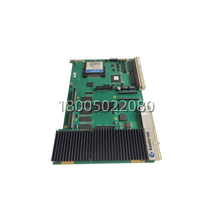
Note: The 1MRK002246-BC is an internal PCB, not a DIN-rail module. It sits downstream of the bay’s primary PSM (e.g., 1MRK002239-BB or PSM03). Verify host compatibility — RET/REC/REx-series and certain ACS drive control sections use this board, but ordering-code cross-checks are recommended before purchase.
Technical Principles and Innovative Values
- Innovation Point 1: Multi-Rail Derivation from a Single 24 V Input. The 1MRK002246-BC doesn’t just regulate one voltage — it takes the bay’s 24 V DC primary rail and generates three isolated/logically separated rails (+5 V for digital logic/DSP, +12 V for communication transceivers and some analog, –12 V for op-amp biasing on the analog input stages). This consolidation means one small PCB replaces what would otherwise be three discrete DC-DC bricks, saving space inside crowded relay enclosures.
- Innovation Point 2: Four-Fold Protection Without External Fusing. The 1MRK002246-BC integrates input reverse-polarity protection (critical when a panel tech accidentally lands 24 V backwards during a rushed maintenance window), plus output short-circuit, over-current, and over-temperature lockout. When any threshold trips, the board latches off rather than frying downstream — the CPU board and analog front-end survive what would otherwise be a cascaded failure. Reset requires a power cycle, which forces a deliberate check rather than an automatic retry into a fault.
- Innovation Point 3: Silent, Fanless, Convection-Optimized Layout. At 15–30 W and >80 % efficiency, the 1MRK002246-BC runs cool enough for pure convection cooling inside the relay cubicle. The PCB layout places the switchers away from the edge-connector side (where the CPU board’s sensitive analog sections sit) and uses thermal relief vias to spread heat into the host chassis standoffs. In a substation relay room where ambient can sit at +55 °C for weeks during summer, this thermal discipline keeps the 1MRK002246-BC from becoming the failure point it was designed to prevent.
Application Cases and Industry Value
A Nordic transmission utility running a fleet of ABB REF615 and RET670 bays standardized the 1MRK002246-BC as a “tier-2 spare” — tier-1 being the primary PSM (1MRK002239-BB), tier-2 being this logic-rail board. The decision followed a 2022 incident where a lightning-induced surge on the station 24 V DC bus caused a 1MRK002246-BC in Bay 7 to latch on OCP; the primary PSM survived, but the REF615 went black because its +5 V logic rail collapsed. The utility had no spare board on site, so the entire bay was out for 36 hours waiting for a courier. Post-incident, every substation storeroom now carries two 1MRK002246-BC boards per relay type. Over the following 18 months, three bays across two stations took board-level swaps for the same failure mode — each swap took under 15 minutes, each avoided a full relay replacement estimated at €6–8 k plus a day of SAT. The protection engineer’s note: “The PSM gets the glory because it’s the 24 V feed everyone measures first. But the 1MRK002246-BC is the one that actually kills the bay when it goes.”In a separate pulp-mill deployment, an ABB ACS800 drive’s control section uses a 1MRK002246-BC (or functionally equivalent 1MRK-family logic PSU) to derive +5 V / ±12 V for the AMC board stack. When the drive started throwing sporadic “Chassis Communication Loss” faults during grade changes (high vibration periods), the techs initially blamed the fiber link. Swapping the 1MRK002246-BC cured it — one of the +5 V rail’s bulk caps had dried, causing voltage dip during vibration that reset the communication ASIC. Board swap, 12 minutes, drive back online. The mill now stocks the 1MRK002246-BC alongside the control board (1MRK000161-AAR01) as the “drive brain spares pair.”