WhatsApp:+86 18150087953 WeChat: +86 18150087953
  Email:
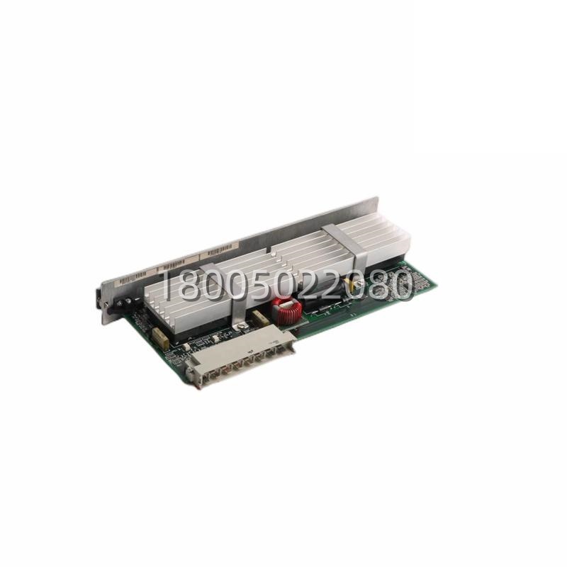
Application Scenarios
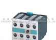
In an automotive stamping press line, after a safety stop triggered by a light curtain breach, the machine enters a safe, locked-out state. Before production can resume, a specific, secure procedure must be followed: a technician must first perform a functional test of the safety system, then visually confirm the hazard zone is clear, and finally authorize a restart. The ABB S185TBC Control Board is the dedicated interface for this critical workflow. Mounted on the main control panel, it provides a keyswitch-protected Test mode, a distinct Reset/Start pushbutton, and associated indicator lamps. To test, the technician turns the key, activating the S185TBC‘s test circuit, which allows the safety PLC to sequentially test its outputs (e.g., by pulsing safety contactors) while monitoring for correct feedback—all initiated and supervised through this board. After a successful test and zone clearance, pressing the guarded Reset button sends a validated, dual-channel signal through the S185TBC to the safety PLC, which then permits the main drive to be re-energized. This board formalizes a critical human-machine interface, directly addressing the pain points of unauthorized resets, untested safety functions, and unclear system state indication.
Parameter
| Main Parameters | Value/Description |
|---|---|
| Product Model | ABB S185TBC (SAfT185TBC) Control Board |
| Manufacturer | ABB (Asea Brown Boveri) |
| Product Category | Safety Operator Interface Board / Test Reset Start Module |
| Primary Function | Provides monitored pushbutton and keyswitch interfaces for Test, Reset, and Start commands to a safety controller. |
| Input Elements | Keyswitch (for Test/Manual mode selection), Pushbutton (for Reset/Start), potentially a separate Enable Switch. [All with dual-channel monitored contacts] |
| Output Elements | LED Indicators for status: Power On, System Ready, Fault, Test Active, Machine Running. |
| Contact Type | Force-guided (positively driven) relay contacts or solid-state safety outputs for signal integrity. |
| Output Signals | Dual-channel, cross-monitored digital signals to the safety PLC (e.g., for “Reset” and “Start Permissive”). |
| Diagnostic Capability | Continuity monitoring of input circuits, cross-fault detection on output signals, internal self-check. |
| Power Supply | 24V DC (typical) from a safety-rated or monitored source. |
| Connection | Removable screw terminal blocks or plug-in connectors for reliable field wiring. |
| Mounting | Front-of-panel mounting for operator access, with DIN-rail or direct chassis mount for the internal board. |
| Front Panel Rating | Typically IP54 or IP65 for dust/water protection on the operator interface. |
| Safety Standards | Designed for integration into control systems meeting IEC 62061, ISO 13849 (up to PL e), and supports SIL 3 applications. |
| Compatibility | Interfaces with ABB SAfT systems, AC500-S safety PLCs, and other safety controllers accepting monitored manual inputs. |
Technical Principles and Innovative Values
The ABB S185TBC is engineered to manage the inherently risky human interaction with a safety system, using robust hardware logic to prevent unsafe commands and provide unambiguous feedback.
- Innovation Point 1: Sequenced, Monitored Mode Logic to Enforce Safe Procedures. The board incorporates hardwired or firmware-based logic that enforces a mandatory operational sequence. For example, the Test function is often only accessible via a keyswitch, physically limiting authorization. The board’s logic may requirea successful test cycle to be completed before the Reset/Start button signal is even enabled or acknowledged by the safety PLC. This physical and logical interlock prevents an operator from simply bypassing a test and resetting a fault, ensuring safety functions are verified before each restart—a core innovation for procedural safety.
- Innovation Point 2: Dual-Channel, Cross-Monitored Inputs with Anti-Tie-Down. The pushbutton and switch inputs are designed with dual, separate contact blocks. The S185TBC continuously monitors these two channels. For a valid “Reset” command, both channels must close and open in a precise time window relative to each other. This design detects common failures like a welded contact, a stuck button, or a short circuit, preventing a single fault from generating a false “Reset” signal. This is known as anti-tie-down and cross-monitoring, which is essential for achieving high Performance Levels (PL) and Safety Integrity Levels (SIL).