WhatsApp:+86 18150087953 WeChat: +86 18150087953
  Email:
Description:
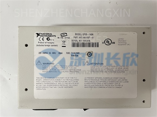
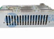
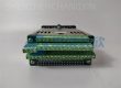
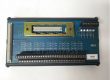
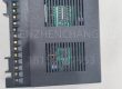
The NI GPIB-140A (with part number variants like 186135H-01L) is a Fiber Optic GPIB Extender (also referred to as a bus extender or repeater) manufactured by National Instruments (NI) . Its primary function is to overcome the inherent distance and device load limitations of the traditional IEEE 488 (GPIB) bus standard . By converting electrical GPIB signals to optical signals for transmission over fiber optic cables, it allows GPIB-based test and measurement systems to operate reliably over distances up to 1 kilometer and connect up to 26 devices, far exceeding the standard 20-meter cable length and 15-device limits . It operates in a software-transparent manner, requiring no modifications to existing GPIB applications or instrument drivers .
Note: Some sources may refer to a “GPIB-140A” as a PCI-based GPIB controller card . However, the predominant and well-documented function of the GPIB-140A product family is as a fiber optic extender. The part number “186135H-01L” is consistent with this extender function .
Application Scenarios:
In an automotive test facility, a central control room houses the test executive software and GPIB controller, but the environmental chamber containing the device under test (DUT) and numerous GPIB instruments (power supplies, oscilloscopes, spectrum analyzers) is located 500 meters away in a separate, vibration-isolated building. Running standard GPIB copper cables this distance is impossible due to signal degradation and the 20-meter limit.
A pair of NI GPIB-140A units is deployed. One unit is placed in the control room, connected to the GPIB controller. The other is placed inside the environmental chamber’s instrument rack. A standard GPIB cable connects the chamber’s instruments to the local GPIB-140A. A single, lightweight 1 km fiber optic cable is run between the two GPIB-140A units. The system now functions as a single, logical GPIB bus. Engineers in the control room can send commands and retrieve data from all remote instruments as if they were locally connected, enabling fully automated, long-duration reliability tests without signal integrity issues .
Key Parameters:
Note: Specifications such as power supply and operating temperature may vary slightly between different versions or part numbers (e.g., 186135G-01. 186135H-01L). Always verify with the official NI datasheet for the exact variant.
Technical Principles and Innovative Values:
The NI GPIB-140A operates on the principle of electro-optical conversion and signal regeneration to extend the GPIB bus.
Innovation Point 1: Breaking the Distance Barrier with Fiber Optics. The fundamental innovation is replacing the lossy, capacitance-limited copper GPIB cable with low-loss, noise-immune fiber optic cable . Each GPIB-140A unit contains transceivers that convert the parallel electrical GPIB signals (data, handshake, control lines) into a serialized optical data stream for transmission over the fiber . This allows the GPIB bus to span up to 1 km without signal degradation, enabling remote placement of test equipment in clean rooms, environmental chambers, or hazardous areas far from the control computer .
Innovation Point 2: Increasing System Capacity and Load Driving. The extender acts as an active repeater, regenerating the GPIB signals . This effectively resets the electrical load count on the bus. By strategically placing extenders, the total number of addressable GPIB devices in a system can be increased from the standard 15 to 26 . This is crucial for complex test stands integrating many instruments .
Innovation Point 3: Software Transparency and High-Speed Buffering. The GPIB-140A is designed to be software-transparent . It does not require any changes to existing GPIB application software or instrument drivers . It also features buffered transmission technology . In buffered mode, data is temporarily stored and error-checked before being forwarded, ensuring high data integrity over long links, especially at the higher HS488 speeds (up to 2.8 MB/s) . This combination preserves existing software investment while enhancing performance and reliability .
Application Cases and Industry Value
Case Study: Distributed Satellite Payload Test System.
A aerospace contractor needed to test multiple satellite communication payloads simultaneously. The payloads were housed in large, separated anechoic chambers to prevent interference, while the control and data acquisition servers were centralized. Each payload test required control of over 10 GPIB instruments (signal generators, network analyzers, power meters).
Using multiple NI GPIB-140A extender pairs, they created a “star” topology. A central GPIB controller in the server room connected to several GPIB-140A units. From each, a fiber optic cable ran to a corresponding GPIB-140A in a distant anechoic chamber, which then connected to that chamber’s cluster of instruments.
Result: The system successfully controlled over 40 GPIB instruments across four separate chambers from a single control point, with cable runs exceeding 300 meters. The fiber optic links were immune to the electrical noise generated by high-power amplifiers in the chambers. The setup reduced cabling complexity and cost compared to alternative solutions (like multiple remote controllers), accelerated test setup, and provided the flexibility to reconfigure instrument clusters easily. The project manager estimated a 30% reduction in integration time and eliminated intermittent communication errors previously caused by long copper runs.
Related Product Combination Solutions
The NI GPIB-140A is a key component in extending legacy GPIB systems.
GPIB Controllers: To drive the extended bus, you need a GPIB controller card in the host computer, such as:
NI PCI-GPIB: A PCI bus GPIB interface card .
NI GPIB-ENET: An Ethernet-to-GPIB controller for network-based control .
GPIB Cables: Standard IEEE 488 cables to connect instruments to the local GPIB-140A unit and to connect the controller to its GPIB-140A.
Fiber Optic Cables: ST-to-ST multimode fiber optic cables of the required length (up to 1 km) to link the two GPIB-140A extenders.
GPIB-140A/2: An enhanced variant of the extender capable of supporting distances up to 2 kilometers .
GPIB Instruments: Any device with a standard IEEE 488 interface, such as oscilloscopes, multimeters, signal generators, and power supplies from vendors like Keysight, Tektronix, and Keithley.
Installation, Maintenance, and Full-Cycle Support
Installation: Installation is straightforward. Each GPIB-140A unit requires AC power . One unit is placed near the GPIB controller and connected via a short GPIB cable. The other unit is placed near the remote instrument cluster and connected via GPIB cables to the instruments. A pre-terminated ST-type fiber optic cable is then connected between the two units . No software configuration is needed; the system is plug-and-play.
Maintenance: The solid-state design ensures high reliability. Primary maintenance involves ensuring fiber optic connectors are clean and undamaged to prevent signal loss. Status indicators on the units can help diagnose link integrity. If a unit fails, it can be replaced without disturbing the field wiring (GPIB and fiber cables), minimizing downtime.
We provide comprehensive support for the NI GPIB-140A fiber optic GPIB extender and related GPIB integration solutions. This includes system design consultation, supply of genuine NI hardware and compatible cables, installation guidance, and troubleshooting support to ensure your extended test and measurement systems operate reliably.