 WhatsApp:+86 18005022363 WeChat: +86 18005022363
  Email:
Description
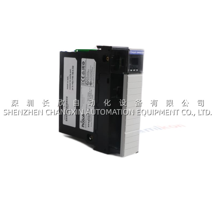
Application ScenariosA steel wire drawing line running two 45 kW DC motors (payoff + take-up) on a Reliance GV3000/SE 2-axis drive kept tripping DC-link overvoltage (OV) during rapid deceleration of the take-up reel — the original single brake resistor, sized for steady-state regen, couldn’t absorb the 2-second 120% regen spike when the dancer arm snapped taut, costing the plant ~45 minutes of re-threading per trip. The retrofit added a DBM-04 (CY1603B3) between the GV drive’s DC-link bus and two 15 Ω / 12 kW brake resistors (one per axis, cross-coupled via the DBM-04‘s internal steering diodes). The DBM-04 monitors Vdc per axis; when the link crosses the 750 V threshold (set via DIP on the CY1603B3), it PWM-switches the per-axis IGBT to clamp the bus. Because the DBM-04 is dual-axis, regen from the payoff reel (motoring in reverse = generator during payout acceleration) can be routed to the take-up resistor during shared windows — something a single-axis brake can’t do. Post-install, OV trips dropped from 3–4/week to zero across an 8-month campaign, and the line’s top speed was nudged up 6% because the drive no longer had to “derate deceleration ramp” to protect the DC link.
Parameter
| Main Parameters | Value/Description |
|---|---|
| Product Model | DBM-04 (Board P/N: CY1603B3) |
| Manufacturer | Moog (Reliance Electric legacy, GV-series ecosystem) |
| Product Category | Dual-Axis Static Trip / Dynamic Brake Module |
| Compatible Drives | Reliance GV3000/SE, FlexPak Plus, MinPak Plus (2-axis configurations) |
| Number of Axes | 2 (independent chopper per axis, shared DC-link sense) |
| DC Link Voltage Range | 300–700 V DC (460 V AC input drive class) |
| Chopper IGBT Rating | 75 A / 1200 V (per axis, internal) |
| Continuous Brake Current | ~25–40 A per axis (resistor-dependent) |
| Peak Brake Current | ~80 A for 2 s |
| Trip Functions | I²t motor overload, DC-link OV, brake-resistor PTC thermal |
| Armature Sense Input | 0–10 V or 4–20 mA from drive’s armature shunt (I²t source) |
| Mounting / Form Factor | PCB with standoffs, panel-mount in drive cubicle |
| Operating Temp | 0°C to +50°C (cabinet ambient) |
Technical Principles and Innovative Values
- Innovation Point 1: Dual-Axis Regen Sharing via Cross-Steering Diodes. In a 2-axis winder, one motor is almost always regenerating (unwind payoff) while the other is motoring (take-up draw). A single-axis brake wastes the payoff’s regen energy as heat on its resistor while the take-up side may still OV-fault. The DBM-04 steers regen current from either axis to either resistor (or a shared resistor bank) based on which chopper is active, maximizing resistor utilization. On the CY1603B3 board, jumper J1–J4 select the steering mode — “independent,” “shared-A-primary,” or “shared-B-primary.”
- Innovation Point 2: Integrated Static Trip (I²t) Without Extra Overload Relay. The DBM-04 accepts a 0–10 V armature-current sense from the GV drive’s 50 mV / 200 mV shunt and runs an internal I²t accumulation model. If the motor thermal limit is approached (class 10 / 20 / 30 selectable via DIP), the DBM-04 pulls the drive’s ENABLE interlock low — a true “static trip” that replaces the old thermal overload relay on the motor feeder. This matters on wire drawers where ambient in the motor bay hits 55°C and thermal bi-metallic trips drift seasonally; the DBM-04‘s I²t is ambient-invariant.
- Innovation Point 3: Adjustable Chopper Threshold & Deadband. The CY1603B3 carries a 4-position DIP for the DC-link OV threshold (typically 700 / 750 / 800 / 850 V options) and a potentiometer for chopper deadband (hysteresis). This lets the panel builder tune to the actual DC-link capacitor bank and resistor ohm value — e.g., a 10 Ω resistor clamps harder but needs a higher threshold to avoid chatter; a 20 Ω resistor needs a lower threshold. Generic brake modules are fixed at 760 V, which is wrong for half of real installations.
- Innovation Point 4: Brake Resistor PTC Guard. Each axis on the DBM-04 has a 2-pin PTC thermistor input (NTC also accepted on some CY1603B3 revs). If the brake resistor (mounted in a sometimes-poorly-vented cubicle) overheats > 120°C, the DBM-04 inhibits the chopper and latches a FAULT — preventing the “resistor glows red and takes the cubicle with it” scenario that’s sadly common in retrofit jobs where the resistor was sized by catalogue not by duty cycle.
Application Cases and Industry ValueCase 1 – Paper Converting Winder, Western Europe. A 2-drum center-winder on a coaters line runs Reliance FlexPak Plus 2-axis (45 kW unwind / 55 kW wind). Original design had no brake module — regen from the unwind (constant tension, motor acting as generator) was pushed back through the drive’s regen bridge to a line-regenerative unit that kept tripping on utility flicker. The retrofit inserted a DBM-04 (CY1603B3) with a single 10 Ω / 20 kW resistor shared across both axes. The DBM-04‘s J1 jumper set to “shared-A-primary” meant unwind regen always hits the resistor first; wind regen (rare, only during decel) shares the same resistor. Result: line regen unit saw 60% less peak back-feed, and the utility’s flicker complaints dropped below threshold. The plant engineer: “The DBM-04 paid for itself in one utility penalty-charge avoidance.”Case 2 – Elevator Test Rig, East Asia. A 2-motor hoist/bogie test stand (2 × 30 kW DC, GV3000/SE 2-axis) uses the DBM-04 in a different way: both axes can regenerate simultaneously during a loaded descent stop. The original single 15 Ω resistor couldn’t absorb both axes at once (chopper duty > 100% for 4 s). The fix: two 15 Ω resistors, DBM-04 in “independent” steering, plus the CY1603B3‘s I²t wired to trip the drive if either resistor PTC (mounted on the resistor casing) exceeds 110°C. The rig ran 14 months of continuous certification testing with zero brake-related faults. Maintenance note: “We used to replace the resistor every 10 months. With the DBM-04 PTC guard, we’re at 22 months and the resistor’s still within spec.”Related Product Combination SolutionsThe DBM-04 (CY1603B3) lives inside a Reliance GV-series 2-axis drive cubicle; here are the natural companions:
- GV3000/SE 2-Axis Drive (e.g., GV3000-SE 460 V, 55 kW) – The host drive; the DBM-04 bolts (electrically) across its DC link terminals (L+/L-) and senses armature via the drive’s shunt.
- FlexPak Plus 2-Axis (1Q or 4Q config) – Smaller sibling of GV3000; the DBM-04 also works here (DC link voltage window 300–700 V matches).
- DBM-02 – Single-axis version of the same module; if your application is 1-axis (e.g., a single unwind only), the DBM-02 halves the footprint and cost.
- CY1603B1 / CY1603B2 – Earlier board revisions of the same DBM-04; B3 adds the PTC input per axis (B1/B2 only had OV + I²t). If you’re repairing a legacy cubicle with B1, the B3 is a drop-in upgrade — just note the PTC pins will be NC if your resistor isn’t PTC-equipped.
- Brake Resistors (15 Ω / 12 kW, 10 Ω / 20 kW, etc.) – The load side of the DBM-04; sizing rule of thumb: R ≈ (Vdc_threshold / I_peak_regen). We can cross-spec if you tell us your motor kW and decel ramp.
- 200 A : 50 mV Armature Shunt – The current sense source for the DBM-04‘s I²t; if your GV drive doesn’t already have one on the armature, you’ll need it for the static trip function to work.
.jpg)
-300x300.jpg)