WhatsApp:+86 18005022363 WeChat: +86 18005022363
  Email:
Description
Product Overview
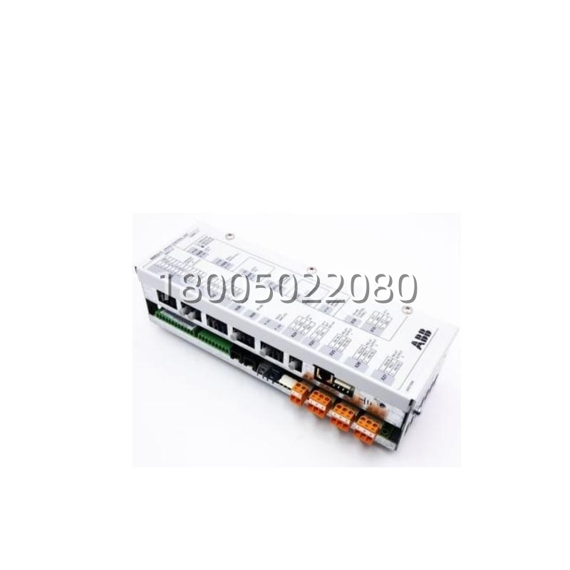
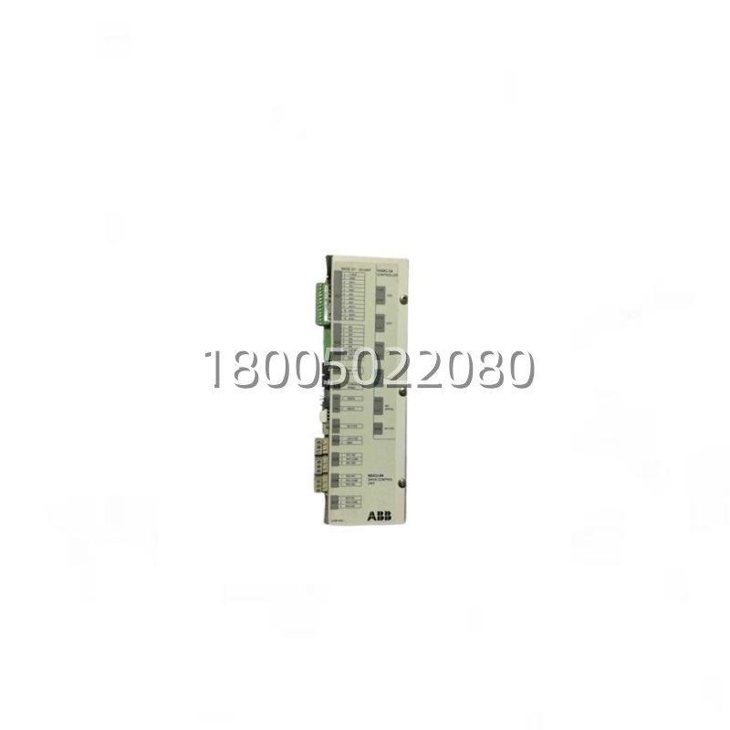
The ABB NDCU-04 is the standard non-programmable Drive Control Unit within ABB’s ACS800 drive family, engineered as the single-axis control brain for ACS800 single-drives and for each inverter module inside an ACS800 MultiDrive (MD) chassis. Evolving from the ACS600-era NDCU ancestors, the ABB NDCU-04 implements ABB’s Direct Torque Control (DTC)-centric vector algorithm — although in ACS800 the control flavor is “vector + DTC hybrid” depending on firmware — handling the torque/speed cascade, flux estimation, flux-braking coordination, and protective supervision (overcurrent, overtemperature, earth-fault, motor-phase loss) that the power stack (AINT interface → AGDR/AGPS IGBT gate-driver) executes. The NDCU-04 is deliberately “non-programmable” — unlike its sibling NDCU-04P which opens a CoDeSys runtime for custom CFC-like logic — meaning the NDCU-04 runs ABB’s sealed drive firmware and exposes only parameter-level tuning (Group 99 motor data, Group 20 limits, Group 30 I/O, Group 40…49 DTC/vector, Group 50…59 application macros). This sealed-firmware approach is exactly why fleets of cranes, winches, conveyors, pumps, fans, and paper-machine sections standardize on the NDCU-04: the drive CU behavior is ABB-validated, no customer-code can corrupt the current loop, and commissioning is parameter-entry, not software-debug.The ABB NDCU-04 mounts in the control-section of an ACS800 inverter module (the upright book-shaped unit that slides into the MD chassis, or the control-half of a wall-mount single-drive). It interfaces downward to the power stack through the AINT-14 (or AINT-12 on older) interface board via the internal 20-pin ribbon + power pins, and upward to the operator through a detachable control panel (NIEDA / NIMP class) plugged into the NDCU-04‘s front fascia, plus fieldbus connectivity through a piggyback module (NETH-21 for Profibus DP, NETH-01 for DeviceNet, etc.) that seats on the NDCU-04‘s expansion header. The unit draws 24 V DC from the ACS800 control-section SMPS (derived from the drive’s internal 3-phase aux or external 24 V DC standby), consumes modest current (~0.5–1 A ballpark on the 24 V rail), and communicates process data (speed actual, torque actual, fault word, status word) to the plant PLC over the fieldbus telegram while accepting speed/torque references and control words (start/stop, reset, enable) from the same telegram.Mechanical footprint is compact — roughly a tall Euro-card profile that clips into the ACS800 inverter’s control-section DIN/card cage, with the front panel exposing the panel socket, status LEDs (run, fault, ready), and the expansion header under a cover. Operating envelope 0…+50 °C (some sources extend to +60 °C with derating), IP20 (control-section internal, behind the drive’s sheet-metal door). The NDCU-04 is the “default” CU shipped on the vast majority of ACS800 singles and MD inverter slots unless the OEM/project spec explicitly called for the -04P programmable variant — which means installed base of NDCU-04 globally is massive across cranes, marine winches, paper machines, mining conveyors, cement kiln ID fans, and water/wastewater pump stations.
Technical Specifications
| Parameter Name | Parameter Value |
|---|---|
| Product Model | NDCU-04 |
| Manufacturer | ABB Oy / ABB Drives |
| Product Type | Drive Control Unit (Non-Programmable), ACS800 Family |
| Compatible Drive | ABB ACS800 SingleDrive & ACS800 MultiDrive (per inverter module) |
| Control Algorithm | Vector control (DCS800/ACS800 DTC/vector hybrid firmware) |
| Programmability | Non-programmable (sealed ABB firmware; parameter-tuning only) |
| Downstream Interface | AINT-14 / AINT-12 (power-stack interface board) |
| Upstream / Panel | NIEDA / NIMP control panel (front plug), NETH-x fieldbus piggyback |
| Expansion | 1× expansion header (NETH, AIM-02, etc.) |
| Power Supply | 24 V DC (from ACS800 control-section SMPS) |
| Control Inputs (via AINT/AIM) | Start/Stop, Enable, Reset, Ref via fieldbus or analog DI |
| Reference Inputs | Speed ref (fieldbus or ±10 V AO from PLC), Torque ref (fieldbus) |
| Protective Functions | Overcurrent, overtemperature, earth fault, motor phase loss, HW overcurrent |
| Operating Temperature | 0 … +50 °C (derating to +60 °C per ABB docs) |
| Protection | IP20 (control-section internal) |
| Mounting | ACS800 inverter control-section card cage / DIN |
| Sibling Variant | NDCU-04P (programmable, CoDeSys runtime) |
| Order Code (typical) | 3AUA0000027424 (verify against ABB current listing) |
Main Features and Advantages
Sealed Vector Firmware, Zero Customer-Code Risk. The defining trait of the NDCU-04 versus the -04P is what it doesn’tallow: no CoDeSys download, no custom CFC blocks, no “clever” application logic that a site electrician might tweak and forget. The NDCU-04 runs ABB’s factory-validated ACS800 drive firmware — DTC/vector current loop, flux estimator, speed-PI outer loop, flux-braking coordinator, protection state-machine — and exposes configuration only through parameter Groups 1–99 as seen on the NIEDA panel or over fieldbus (Profibus PPO type, Modbus registers). For fleet owners — think a pulp mill with 80 ACS800 inverter modules across the digester, washer, bleach, and machine-hall drives — standardizing on NDCU-04 means every CU behaves identically, every fault code maps to the same ABB manual, and every commissioning engineer uses the same parameter workbook. The -04P certainly has its place (OEMs building custom winder logic on the CU itself), but for 80 % of “standard drive” duties the NDCU-04 is the right-cost, right-risk choice.ACS800 Single + MultiDrive Architecture Fit. In an ACS800 MultiDrive chassis, each inverter module (the “book” that holds IGBTs, DC-link caps, gate-driver) gets exactly one CU — and that CU is the NDCU-04 in the default build. A 6-inverter MD chassis (common on crane-main-hoist + trolley + bridge triples, or paper-machine section drives) thus holds six NDCU-04 units, each owning its motor’s vector loop, each talking fieldbus independently (or via the common fieldbus piggyback topology ABB supports). In a single-drive wall-mount, the NDCU-04 is the only CU in the box. This 1-CU-per-inverter discipline means spare strategy is simple: one NDCU-04 hot-spare covers any inverter slot in the plant’s ACS800 population, single or MD. Contrast with platforms where the CU is shared across inverters — there, a CU failure kills multiple motors; with NDCU-04, a failure kills exactly one inverter, limiting the outage radius.AINT / AIM / NETH Expansion Ecosystem. The NDCU-04 doesn’t stand alone — it’s the center of a small stack. Downward: AINT-14 (or AINT-12) is the interface between the NDCU-04 and the power stack — ribbon + power pins carry PWM gating, DC-link voltage sense, motor-phase current sense (via AGDR/AGPS shunts), and brake-chopper control. The AINT also lands the 24 V DC standby and the motor-temperature PTC/KTY input. Upward/expansion: the NDCU-04 front has a panel socket for NIEDA (basic 2-line LCD) or NIMP (larger graphic) — the panel is detachable, so the NDCU-04 can live deep in an MCC and the panel cable runs to the door. The expansion header under the cover accepts NETH-21 (Profibus DP, 12 Mbit/s, PPO-2/3/5 typical), NETH-01 (DeviceNet), or NETH-x Ethernet variants depending on era — this is how the NDCU-04 talks to the plant S7-400 / AC500 / 800xA. A third companion is AIM-02 (additional digital I/O + analog I/O piggyback) if the inverter needs more than the AINT’s baseline DI/DO/AI. This modularity means the NDCU-04 itself stays lean — no “kitchen sink” component cost — and the plant adds only what the application needs.Diagnostic LED & Fault Architecture. The NDCU-04 front fascia carries Run (green), Fault (red), and Ready/Enable LEDs that are visible through the ACS800 control-section window without opening the drive door — critical for a quick “is it the CU or the power stack?” triage. Fault codes (e.g., F001 overcurrent, F002 DC overvoltage, F003 overtemperature, F004 earth fault, F007 AI loss) display on the NIEDA panel and are also mapped onto the fieldbus status word (PPO telegram’s STS1/STS2), so the plant SCADA sees the fault code within the same scan that the drive trips. The NDCU-04 also supports ABB’s DriveWindow PC tool over the panel’s optical port or over fieldbus (via NETH’s service channel) — during commissioning, an engineer can stream oscilloscope traces of torque, speed, DC-link voltage, and phase currents directly from the NDCU-04‘s internal buffers, watching flux-transition or braking-current in real time without probes on the IGBTs. This is a major advantage over “dumb” drive CUs that only give you parameter tables.24 V DC Standby & Controlled Stop. The NDCU-04 (and the AINT’s 24 V circuit) can be fed from an external 24 V DC standby supply so that when the plant’s 480 V / 690 V main drops, the NDCU-04 stays alive long enough to execute a controlled stop (decelerate via residual DC-link, then drop enable) and log the fault cause, rather than just collapsing. On crane applications especially, this “24 V alive through mains loss” is what lets the NDCU-04 finish a bridge deceleration and set the mechanical brake cleanly instead of a free-fall scramble. The external 24 V DC also powers the NIEDA panel and the NETH fieldbus piggyback, so the plant SCADA can still read “drive faulted — mains lost” after the event.