WhatsApp:+86 18005022363 WeChat: +86 18005022363
 Email:

Description
Application Scenarios
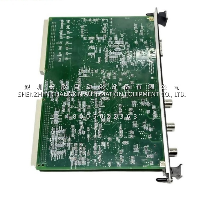
A Frame 7FA is at base load on a July afternoon. The three controllers are voting cleanly, the fuel stroke reference is steady, and the only thing moving on the VCMI front panel is the binary 1-2-4-8 LEDs ticking over with each VME scan. Then the IONet BNC chain to the remote I/O rack sees a bad barrel connector after a cabinet slam. A lesser card would go silent and hand the controller a “missing I/O” fault that looks exactly like a turbine problem.The GE IS215VCMIH2CB does something more useful: the TX/RX/CD LEDs on the affected port stop their pattern, the Fail LED stays dark because the card itself is fine, and the diagnostic log points at one IONet segment. The shift finds the crushed terminator in twenty minutes, screws a 50 Ω cap back on, and the unit never leaves auto. The turbine did not care about the connector; the operators did, and the card gave them the right clue instead of a generic “communications lost” trip.
Parameter
| Parameter | Value / Description |
|---|---|
| Product Model | IS215VCMIH2CB — the B is the board-revision / EMI-enhancement level; quote the full string, not just “VCMI” |
| Family / Short Name | VCMI-H2CB; also logged as IS215VCMI bus-master assembly |
| Manufacturer | GE / GE Fanuc, Speedtronic line (later GE Energy / GE Vernova heritage, USA) |
| Product Category | VME bus-master communication interface board — not an I/O card, not a CPU, not a media converter |
| System Platform | Speedtronic Mark VI and Mark VIe turbine control; simplex and TMR rack configurations |
| Form Factor | 6U VME, single-slot width (0.787 in), standard VME C-size edge connectors (P1/J1, P2/J2). The “2-slot wide / 10-slot backplane / VME64x” claims online belong to a different SKU — do not use them |
| Processor | Texas Instruments TMS320C32 32-bit floating-point DSP — owns the bus arbitration and the IONet timing so the main controller spends its cycles on the control law, not on the traffic cop |
| Memory | 32 KB dual-port SRAM, 32-bit transfer width; Flash program store (VCMIH_C fit: 4,096 K × 8). The dual-port RAM is the whole point — VME and the DSP read/write the same buffers without stealing each other’s cycle |
| VMEbus Role | Bus master, VME D1.1-class signalling; arbitrates the backplane, assigns rack board IDs, schedules reads/writes to the local I/O and to the controllers |
| IONet Ports | 3 × 10BASE2, BNC coaxial, 10 Mbps — three independent segments. This is the H2 differentiator: H1 is single-port, H2 is triple-port. Each port has its own TX / RX / CD LED |
| Serial Port | 1 × RS-232C, 9-pin D-sub (DB9) — local console, diagnostics, firmware work. GE-documented default is 9,600 baud |
| Frame / Scan Timing | Simplex: 10 ms (100 Hz) frame; TMR: 40 ms (25 Hz) on the published VCMIH_C fit. Some site Toolbox builds log a 20 ms / 50 Hz heartbeat — both are a function of the application build, not the silicon |
| Diagnostics | Run / Fail / Status LEDs + binary 1, 2, 4, 8 rack-address/data-activity indicators; manual reset button; power-rail and ground-fault monitoring |
| Supply Rails Monitored | +5 V, ±12 V, ±15 V and +28 V (the rack supplies them; the board flags a rail out of tolerance as a self-test failure) |
| Power Draw | Backplane-fed; typical quoted range +5 V @ ~1.8–2.5 A with modest ±12 V / ±15 V auxiliary draw. Measure at the slot under full I/O traffic — aged rack supplies dip just far enough to cause “ghost” VME timeouts |
| Isolation / Noise | Transformer-isolated IONet path, ferrite beads and three transformer assemblies on the PCB; the CB revision adds the enhanced EMI filtering and screening |
| Temperature | −30 °C to +65 °C on the CB/wider-temp build; conservative-site fit is 0 to +60 °C. (The “−40 to +70 °C” and “IP30 / DIN-rail” claims are other GE boards, not this one.) Storage −40 to +85 °C |
| Vibration / EMC | Built to the IEC 60068 shock/vibration and power-plant EMC envelope; conformal-coated PCB, IP20 module level — lives behind the rack door, not in an outdoor cabinet |
| Mechanical | ≈233 × 160 × 20 mm class, 0.45–0.9 kg depending on coating and whether the screw-retainer ships; single-slot, faceplate screw + VME guide rails |
| Hot-Swap? | No. VME bus-master functions are not hot-swap-safe. The rack is powered down, the 5 V / 12 V / 28 V rails confirmed dead, and the backplane pins inspected before extraction. “Hot-swap capable” listings are wrong for this SKU |
| Safety / SIL | The Mark VIeS safety configuration of the wider platform carries the IEC 61508 claim, not the bare IS215VCMIH2CB. Do not write “SIL 3 VCMI” on a procurement spec unless your cabinet is a documented VIeS build — and even then the certificate sits on the system configuration, not on this card |
| Lifecycle | Mature / EOL-trending legacy part; long OEM lead times. Authenticity, board rev, and firmware/ToolboxST version match matter far more than whether the anti-static bag is sealed |
Technical Principles and Innovative Values
Innovation Point 1 — It is a traffic cop with its own brain, not a passive backplane driver. The IS215VCMIH2CB runs the VME arbitration on the TMS320C32 DSP, independently of the rack’s main turbine controller. While the controller is busy with speed regulation, fuel staging and protection math, the VCMI is handing out IDs, packing I/O snapshots and policing the three IONet segments. That separation is why a busy I/O scan never steals time from the control law — and why a VME slot-fight looks like a VCMI fault, not a controller fault.Innovation Point 2 — Three IONet ports are a TMR architecture, not a port-count flex. A single coax segment between racks is a single point of failure, and a daisy-chain with a bad terminator takes the whole thing down. The H2 / H2CB triple-port layout gives each redundant path its own 10Base2 segment, so controller A, B and C exchange state over separate physical wires. No external switch, no Ethernet hub, no “we’ll add a media converter later.” It is TMR the way the Mark VI was designed to be TMR.Innovation Point 3 — Dual-port SRAM turns a bus bottleneck into a handshake. The DSP writes the fresh I/O image into one port while the VME master reads the last one from the other. No shared-clock contention, no “I’m half-way through the frame” corruption. In a system where the fuel stroke reference is updated every 10–40 ms and a stale value is a trip, that is not a nice memory trick — it is the reason the voting stays coherent.Innovation Point 4 — The front panel is a diagnostic instrument, not a decoration. Run, Fail, Status and the 1-2-4-8 binary lights tell a field engineer more in thirty seconds than an hour of scrolling alarm history: which IONet port is carrying traffic, whether the DSP passed self-test, and whether the board sees a rail problem. Pair that with the per-port TX/RX/CD triplets and you can diagnose a crushed barrel connector, a missing 50 Ω terminator or a dying rack supply before the controller declares missing I/O.Innovation Point 5 — The B matters, and the CB revision is the quiet quality upgrade. The jump from H2C to H2CB is not cosmetic: better EMI filtering, tighter screening, wider thermal envelope. In a turbine skid or an unconditioned compressor house, that is the difference between a nuisance VME timeout during a VFD-heavy start and a card that rides out the noise. The catch is that the firmware and the ToolboxST/Mark VI Toolkit build must accept the B hardware — a mismatch is the one thing that turns a drop-in spare into a rejected boot.
Application Cases and Industry Value
Case 1 — Frame 7FA, 20 ms heartbeat preserved through a VFD storm. The gas turbine’s control rack had been logging sporadic “VME bus timeout” alarms every few weeks, always during a forced-draft-fan VFD start. The main controller was clean, the I/O cards were clean, and the electricians were about to re-spin the grounding. Before that, the team read the GE IS215VCMIH2CB front panel: Fail dark, Run steady, but the binary 1-2-4-8 pattern stalled for one scan every time the VFD line notched. The CB-revision board’s enhanced filtering was the suspected gap. They swapped in a tested IS215VCMIH2CB, confirmed the 5 V rail at the slot under load (it had been dipping to 4.7 V on the old supply), and the 30-minute nuisance cleared. No software change, no turbine trip, no grounding rework. The maintenance lead’s note: “the card told us it was electrical noise; the old card just couldn’t ignore it.”Case 2 — Steam-turbine TMR, mismatched firmware caught before the outage. A plant upgrading a simplex Mark VI to a TMR fit ordered three VCMI boards from three different sources. Two were H2C, one was the H2CB. On paper they looked interchangeable; in the rack, the B board’s firmware build was one step ahead of the other two and the arbitration vote went silent — exactly the “silent voting failure” every TMR engineer fears. Because the swap was done on the bench with all three cards in a test rack and the IS215VCMIH2CB logs side-by-side, the mismatch was found before the turbine saw it. The fix was one flash cycle and a rule written into the storeroom: H2C and H2CB mix only when the firmware matrix says yes. Three cards, one revision, one bill of material line.Case 3 — Combined-cycle, the 45-minute save. A 500 MW combined-cycle unit dropped off the Mark VI network during a night shift; the operators saw “controller comms lost” and were one minute from a manual derate. The on-site tech went straight to the control rack, saw Fail lit on the VCMI and TX solid on IONet port 2 — the textbook “shorted coax or wrong terminator” signature. He isolated the remote-I/O segment at the BNC barrel, the Run LED came back, and the controller re-acquired inside the 40 ms TMR frame. Total elapsed time, 45 minutes; no lost generation. The root cause was a contractor’s temporary jumper left untterminated after a cable pull. The IS215VCMIH2CB didn’t prevent the mistake — it made sure the mistake was cheap instead of catastrophic.