WhatsApp:+86 18005022363 WeChat: +86 18005022363
  Email:
Description
Application Scenarios
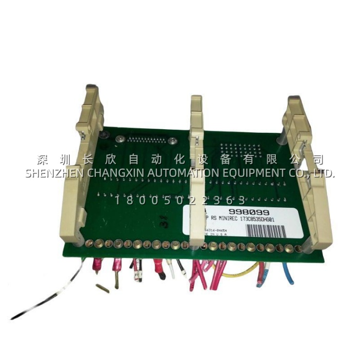
A combined-cycle plant running a GE Mark VI control system on two gas turbines and a steam turbine has, over fifteen years, accumulated the usual accretion of field modifications: a tachometer added during a rotor upgrade, two analog outputs repurposed for a bypass damper, a couple of relay contact circuits borrowed for a lube-oil skid interlock. Every one of those changes terminates somewhere in the control cabinet, and the cabinet’s sanity depends on whether terminations are centralized and labelled or scattered across ad-hoc terminal rails. In installations where GE 173C8535DHG01 is doing the job, all of it — digital inputs, digital outputs, analog in and out, tachometer channels, potentiometer inputs, SSR drives, relay contacts, fault strings — lands on one board with a fixed, documented conductor layout that matches the backplane pin-for-pin.The pain point this solves is not speed or intelligence; it is traceability. When a turbine trips on a spurious digital input at three in the morning, the difference between a twenty-minute fix and a six-hour outage is whether the technician can stand in front of one terminal board, put a meter on a labelled point, and know exactly which CABP backplane pin and which controller tag he is looking at. GE 173C8535DHG01 provides that single point of truth, and because it carries no fuses, jumpers or adjustable hardware, there is nothing on the board that can be left in the wrong state by a previous shift.The second scenario is a Mark VI cabinet refurbishment or drive retrofit, where the existing chassis is being reused and the wiring harness retained. Keeping GE 173C8535DHG01 in the loop means the field cable set does not have to be re-engineered: the same 60 positions, the same J6 and J7 pin mapping, the same mechanical footprint. That converts what could be a re-termination project into a controlled board swap inside a planned outage window.
Parameter
| Main Parameters | Value/Description |
|---|---|
| Product Model | 173C8535DHG01 |
| Manufacturer | General Electric (GE) — Speedtronic / Innovation Series, Salem, Virginia production |
| Product Category | Interface board / Application I/O terminal board (ATBA); passive termination layer, no processor or firmware |
| Alternate Catalog Number | IS200ATBAG1B (ordering variants include IS200ATBAG1BAA1) — confirm both numbers before ordering |
| Compatible Systems | GE Mark VI Speedtronic gas and steam turbine control; GE Innovation Series drive assemblies |
| Upstream Connection | Mates to backplane connectors J6 and J7 on the IS200CABP Control Assembly Backplane Board |
| Backplane Connectors | J6: 36-pin vertical male pin header (4 × 9); J7: 25-pin vertical male pin header |
| Terminal Capacity | One 60-position terminal block, arranged as two rows of thirty, individually labelled by signal group |
| Signal Groups Terminated | Digital inputs (12), digital outputs (13), analog inputs (5), analog outputs (5), tachometer (10), MA pilot (3), MA feedback (2), SSR (2), potentiometer (2), system fault string (3), local fault string (3), relay contacts |
| Connector Ratings | Board-mounted connectors up to 176 V, 1 A max; J6 connectors up to 225 V, 1 A max (excluding CONA_NO / CONA_NC / CONA_C and RLY1–RLY3 COM/NC/NO); J7 rated 50 V, 1 A max |
| PCB Build and Revision | G1 group with normal PCB coating; “B” single-function revision — no fuses, no jumpers, no user-adjustable hardware (external fusing supplied by the installer) |
| Mounting and Physical | Nine screws and washers into standoffs, DIN-rail / cabinet-panel installation; approx. 16 × 16 × 12 cm, approx. 0.8 kg; cable shield along one edge; ESD-sensitive, grounding strap required |
Technical Principles and Innovative Values
Innovation Point 1: Passive by design, which is why it is reliable. GE 173C8535DHG01 contains no active logic, no firmware version to match and no configuration file to restore. In turbine control — where a controller swap can mean software licensing, parameter reload and re-commissioning — a purely passive termination board can be replaced in minutes with zero risk of introducing a configuration error. Its reliability comes from what it does not have.Innovation Point 2: Pin-for-pin backplane mapping that makes troubleshooting linear. Every one of the sixty terminal positions on GE 173C8535DHG01 traces to a defined pin on J6 or J7 of the CABP backplane, grouped and labelled by function. That one-to-one relationship turns fault-finding into a straight line from controller tag to terminal point to field device, instead of the multi-hour tracing exercise that generic terminal rails force on maintenance crews.Innovation Point 3: Integrated cable shielding and geometric separation. The board carries a cable shield along one edge to contain and dress the harness, keeping low-level analog and tachometer conductors physically separated from the outgoing relay and SSR wiring. Signal integrity in a turbine cabinet — where tachometer signals are small and relay circuits are not — depends precisely on this kind of layout discipline.Innovation Point 4: Fixed conductor ratings that remove guesswork. Rather than leaving fusing and protection to ad-hoc decisions, GE 173C8535DHG01 defines per-group voltage and current limits (176 V / 1 A on the board, 225 V / 1 A on J6, 50 V / 1 A on J7) and delegates external fusing to the installer. The result is a termination scheme where every circuit’s limit is documented before the first wire is landed.Innovation Point 5: Revision transparency encoded in the part number. The IS200 prefix identifies the Salem-built Speedtronic family, ATBA the function, G1 the coating and grouping, and the trailing B the functional revision. For GE 173C8535DHG01, that means a maintenance engineer can read the board’s construction and variant directly off its designation — a small thing that prevents the classic and expensive mistake of ordering a look-alike board with a different J6/J7 pin assignment.Innovation Point 6: Revision-aware mechanical compatibility. The ATBA family exists in versions whose J6 and J7 pin assignments differ, and GE 173C8535DHG01 (IS200ATBAG1B) is the revision whose mapping is documented for the CABP backplane pairing. Matching this revision exactly is what preserves the “no field rewiring” advantage during a like-for-like replacement.
-300x300.jpg)