WhatsApp:+86 18005022363 WeChat: +86 18005022363
  Email:
Description
Application Scenarios:
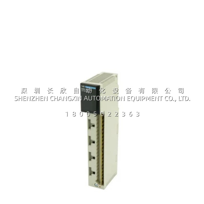
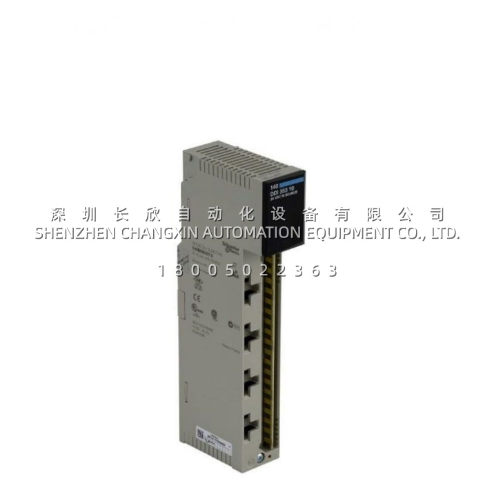
Consider a municipal water treatment plant where the filter backwash sequence depends on dozens of discrete signals: valve position confirmations, high and low level float switches, pump run feedbacks, differential pressure switches across the filter bed. The original installation used 16-point input cards, and as the plant added treatment trains the I/O racks filled up faster than the control room had space. Every expansion meant another rack, another power supply, another bus cable run and another round of panel modifications.Consolidating onto the 140DDI35310 changes the arithmetic. At 32 points per slot, the same signal count occupies half the rack positions, which frees slots, reduces power supply loading and, critically, cuts the number of field cable bundles running into the cabinet. But density is only half the story here. In a wet, electrically noisy environment with long cable runs to remote filter galleries, the failure mode that matters is not a missed fast pulse — it is a false signal caused by ground-potential differences between the field and the control room. The four-group architecture of the 140DDI35310, with its independent commons and 500 Vrms group-to-group isolation, lets the designer segment the wiring by physical area, so a ground disturbance in one gallery cannot corrupt signals from another. That is a design decision, not just a specification.The same reasoning applies wherever 24 V DC discrete signals are dense and electrically exposed: conveyor and material-handling systems in automotive plants where proximity sensors by the hundred track part position; power plant coal handling where belt misalignment, pull-cord and blockage switches sit hundreds of metres from the PLC; mining and minerals operations where vibration and dust punish both wiring and electronics; and substation automation where status contacts from breakers and isolators must be read reliably. In each case the pain point the 140DDI35310 addresses is the combination of limited cabinet space, long and noisy field wiring, and the need to diagnose a single failed field device quickly rather than by elimination.
Parameter:
The values below are taken from Schneider Electric’s published product data sheet for 140DDI35310 and from consistent technical listings.
| Parameter | Value / Description | What it means for you |
|---|---|---|
| Product Model | 140DDI35310 (also catalogued as 140 DDI 353 10) | Order code on the module front label |
| Manufacturer | Schneider Electric (Modicon) | Genuine Schneider Electric hardware |
| Product Category | Low-voltage DC discrete input module | Reads 24 V DC on/off signals from field devices |
| Host Platform | Modicon Quantum automation platform | Fits standard Quantum I/O racks; not interchangeable with other PLC families |
| Discrete Inputs | 32 channels | High density — 32 field signals in one slot |
| Channel Grouping | 4 groups of 8 channels, each with an independent common | Segment wiring by area or voltage source; faults stay inside a group |
| Logic Type | Negative (source) — common wired to 0 V | Match to your field device type; the sink variant is 140DDI35300 |
| Input Voltage | 24 V DC nominal; operating limits 19.2…30 V DC | Tolerates normal supply variation without false states |
| Guaranteed State 1 | −30…−15 V DC; current ≥ 2.5 mA at Us = −14 V | Below these thresholds the module will not reliably register “on” |
| Guaranteed State 0 | −5…0 V DC; current ≤ 0.5 mA | Sensor off-state leakage above 0.5 mA may need a bleeder resistor |
| Input Impedance | 2400 Ω | Modest current draw from field devices and supplies |
| Response Time | ≤ 1 ms, both 0→1 and 1→0 | Captures fast events such as counting and position sensing |
| Absolute Maximum Input | 30 V continuous; 50 V for a 1 ms decaying pulse | Survives inductive kick and wiring transients within these limits |
| Input Protection | Resistor-limited input protection | Overcurrent at the input stage is limited at the hardware level |
| Isolation Group-to-Bus | 1780 Vrms for 1 minute | A field-side fault cannot propagate onto the Quantum backplane |
| Isolation Group-to-Group | 500 Vrms for 1 minute | Signal groups remain electrically independent of one another |
| Addressing Requirement | 2 input words | Occupies 2 words in the PLC input image table |
| Bus Current Requirement | 330 mA from the Quantum backplane | Include in the rack power budget alongside other modules |
| Power Dissipation | 1.5 W + (0.26 W × number of points ON) | Worst case roughly 9.8 W with all 32 points energised |
| Local Signalling | 32 green LEDs for input status; 1 green “Active” for bus communication; 1 red “F” for external fault | Every channel visible at the rack — no multimeter needed for a first check |
| Operating Temperature | 0…60 °C (32…140 °F) | Standard control-cabinet rating; watch dense, poorly ventilated enclosures |
| Storage Temperature | −40…85 °C (−40…185 °F) | Unrestricted long-term storage of spares |
| Humidity / Altitude | Up to 95% RH non-condensing; operating altitude up to 5000 m | Suitable for humid and high-altitude installations |
| EMC Performance | ESD 4 kV contact / 8 kV air (IEC 801-2); 10 V/m radiated immunity, 80…2000 MHz (IEC 801-3) | Holds up in electrically noisy industrial environments |
| Certifications | UL 508, CSA C22.2 No 142, FM Class 1 Division 2, RINA, RMRS, GOST, C-Tick, CE | Approved for industrial, marine and hazardous-location use |
| Module Format / Weight | Standard Quantum single-slot format; 0.3 kg (0.66 lb) net | Drop-in for any standard Quantum I/O slot |
| Wiring Accessory | Requires a 40-pin terminal strip such as 140XTS00200, ordered separately | Budget for the terminal block — it is not included with the module |
Two points worth flagging before you order. First, the logic type: 140DDI35310 is the negative (source) variant, while 140DDI35300 is the positive (sink) variant. They are not interchangeable without rewiring the commons, and some aftermarket listings blur the distinction — confirm which one your field devices and existing wiring require. Second, if your 2-wire proximity sensors have an off-state leakage above 0.5 mA, an input may fail to turn off; a bleeder resistor across the input resolves it. That is a wiring consideration, not a module defect.
Technical Principles and Innovative Values:
- Innovation Point 1 — 32 points in one slot changes the rack economics: The 140DDI35310 concentrates 32 channels into a single Quantum slot. Against a 16-point card, that halves the slots consumed for the same signal count, which cascades into fewer racks, fewer power supplies, fewer bus cables, less cabinet volume and lower installed cost per point. For a plant I/O count in the hundreds, this is the difference between expanding within existing panels and building new ones.
- Innovation Point 2 — Four isolated groups as a fault-containment strategy: The 32 inputs are divided into four groups of eight, each with its own common, isolated at 500 Vrms from the other groups and 1780 Vrms from the backplane bus. This is not merely a protection number. It lets an engineer assign one group per physical area, per power source or per voltage domain, so that a short, a ground fault or a wiring error in one area stays there instead of taking down signals from the whole card. In practice this turns an eight-channel problem into a thirty-two-channel one — or prevents it entirely.
- Innovation Point 3 — Defined switching thresholds instead of ambiguity: With guaranteed State 1 at −30…−15 V / ≥ 2.5 mA and guaranteed State 0 at −5…0 V / ≤ 0.5 mA, the module’s behaviour is fully characterised at the boundaries. Engineers can calculate whether a given sensor, cable length and supply voltage will switch reliably, before installation, rather than discovering intermittent operation in service. The wide hysteresis between the two thresholds is deliberate: it is what makes the module immune to noise sitting near the switching point.
- Innovation Point 4 — 1 ms symmetric response with transient headroom: Response is ≤ 1 ms in both directions, and the input stage tolerates 30 V continuous and 50 V for a 1 ms decaying pulse. Together these mean the module is fast enough for counting, position sensing and high-speed sequencing, while surviving the inductive switching transients that long runs of field cable inevitably deliver. Resistor-limited protection handles sustained overcurrent without a sacrificial fuse to replace.
- Innovation Point 5 — Diagnostics at the point of action: Thirty-two individual green LEDs, plus a green “Active” LED confirming bus communication and a red “F” LED flagging external faults, give three levels of diagnosis in a single glance. A technician can distinguish “field device not switching” from “module not communicating with the CPU” from “external fault on the group” without opening a laptop. In a plant where every minute of downtime has a price, that triage speed is measurable value.
- Innovation Point 6 — Negative logic matched to the dominant sensor population: The 140DDI35310 uses negative (source) logic with the common at 0 V, suiting NPN/switch-to-0V field devices and the wiring conventions common in European and much global industrial practice. Choosing the module whose logic matches the installed sensor base avoids interposing relays or rewiring commons — and, equally important, keeps a plant’s spares pool consistent with the cards already in its racks.